МАСЛЯНЫЙ НАСОС УСТАНОВКА
-
INSTALL TIMING BELT CASE SUB-ASSEMBLY
-
Place a new gasket on the cylinder block.
-
Install the timing belt case with the 5 bolts.
- Torque:
- 22.5 N*m { 229 kgf*cm, 17 ft.*lbf }
-
-
INSTALL OIL STRAINER SUB-ASSEMBLY
-
Install a new gasket and oil strainer with the 2 bolts and 2 nuts.
- Torque:
- 21 N*m { 214 kgf*cm, 15 ft.*lbf, for nut }
- 18 N*m { 184 kgf*cm, 13 ft.*lbf, for bolt }
-
-
INSTALL OIL PAN SUB-ASSEMBLY
-
Remove any old packing (FIPG) material and do not drop any oil on the contact surfaces of the oil pan and cylinder block.
-
Using a gasket scraper, remove all the old packing (FIPG) material from the installation surface.
-
Thoroughly clean all components to remove all the loose material.
-
Using a non-residue solvent, clean both of the sealing surfaces.
Note
Do not use a solvent which will affect the painted surfaces.
-
-
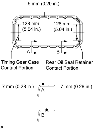
Apply seal packing to the oil pan as shown in the illustration.
Seal packing Toyota Genuine Seal Packing Black, Three Bond 1207B or equivalent Standard seal diameter 5 mm (0.20 in.) Tech Tips
-
Do not apply an excessive amount to the surface, especially near the oil passages.
-
Parts must be assembled within 5 minutes of application. Otherwise the material must be removed and reapplied.
-
After application, immediately remove the nozzle from the tube and reinstall the cap.
-
-
Install the oil pan with the 16 bolts and 2 nuts. Uniformly tighten the bolts and nuts in several steps.
- Torque:
- 18 N*m { 184 kgf*cm, 13 ft.*lbf }
-
-
INSTALL CRANKSHAFT TIMING PULLEY
-
Align the pulley set key with the key groove of the timing pulley.
-
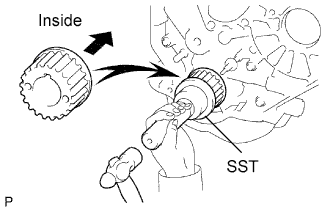
Using SST and a hammer, tap in the timing pulley, facing the flange side inward.
- SST
- 09223-46011
-
-
INSTALL NO. 2 TIMING BELT IDLER SUB-ASSEMBLY
-
Install the spacer and No. 2 timing belt idler with the bolt.
- Torque:
- 33 N*m { 337 kgf*cm, 24 ft.*lbf }
-
Check that the No. 2 timing belt idler moves smoothly.
-
-
INSTALL NO. 1 TIMING BELT IDLER SUB-ASSEMBLY
-
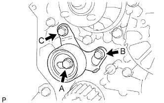
Install the No. 1 timing belt idler with the 3 bolts.
-
Tighten the bolt C.
- Torque:
- 19 N*m { 194 kgf*cm, 14 ft.*lbf, for bolt B. C }
- 44 N*m { 449 kgf*cm, 32 ft.*lbf, for bolt A }
Tech Tips
-
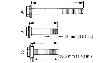
The bolt lengths for bolts A, B and C as follows.
-
Bolt C is combined with the No. 1 timing belt idler.
A 76.5 mm (3.012 in.) B 42.9 mm (1.689 in.) C 41.3 mm (1.626 in.)
-
-
INSTALL WATER PUMP
-
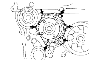
Install a new gasket, the water pump and tension spring bracket with the 6 bolts.
- Torque:
- 23 N*m { 235 kgf*cm, 17 ft.*lbf }
-
-
INSTALL NO. 2 TIMING BELT COVER
-
Install the timing belt cover with the 4 bolts.
- Torque:
- 18 N*m { 184 kgf*cm, 13 ft.*lbf }
-
-
INSTALL CAMSHAFT TIMING PULLEY
-
Install the woodruff key to the key groove of the camshaft.
-
Align the pulley set key with the timing mark facing outward.
-
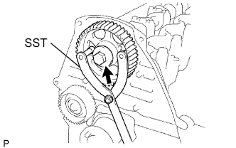
Using SST, install the pulley with the bolt.
- SST
- 09960-10010 ( 09962-01000, 09963-01000 )
- Torque:
- 98 N*m { 1,000 kgf*cm, 72 ft.*lbf }
-
-
INSTALL INJECTION PUMP ASSEMBLY
-
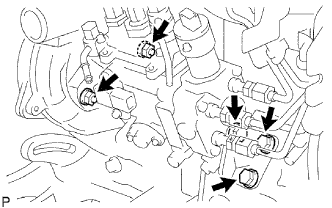
Install the injection pump to the timing gear case, and temporarily tighten the 2 nuts.
-
Install the injection pump stay to the injection pump rear end, and temporarily tighten the 3 bolts.
-
Rotate the pump body to align the marking of the pump flange and timing gear case.
-
Tighten the 2 nuts to install the injection pump.
- Torque:
- 21 N*m { 210 kgf*cm, 15 ft.*lbf }
-
Tighten the 3 bolts to install the injection pump stay.
- Torque:
- 26 N*m { 265 kgf*cm, 19 ft.*lbf, for injection pump stay to cylinder block }
- Torque:
- 26 N*m { 265 kgf*cm, 19 ft.*lbf, for injection pump stay to injection pump }
-
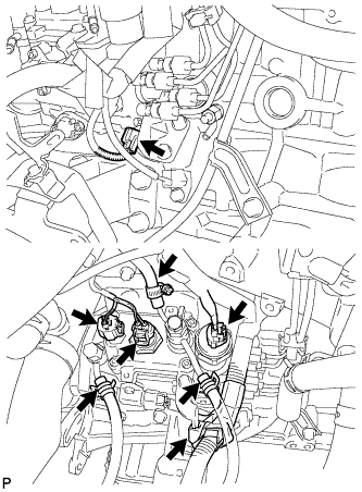
Connect the 3 fuel hoses.
-
Connect the engine speed sensor connector.
-
Connect the spill control valve connector.
-
Connect the correction unit connector.
-
Connect the timing control valve connector.
-
Connect the fuel temperature sensor connector.
-
Connect the engine wire clamp.
-
-
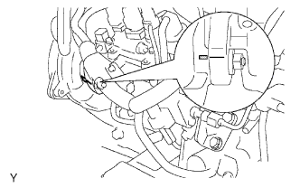
INSTALL INJECTION PUMP DRIVE PULLEY
-
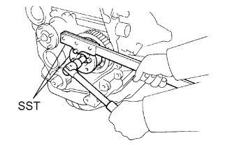
Using SST, install the injection pump drive pulley with the nut.
- SST
- 09213-14010 ( 91651-60865 )
- 09330-00021
- Torque:
- 64 N*m { 650 kgf*cm, 47 ft.*lbf }
-
-
INSTALL INJECTION PIPE SUB-ASSEMBLY
-
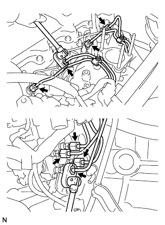
Connect the 2 lower clamps on the intake manifold.
-
Using a union nut wrench, install the 4 injection pipes.
- Torque:
- 24.5 N*m { 250 kgf*cm, 18 ft.*lbf }
-
Secure the injection pipes with the 2 upper pipe clamps and 2 nuts.
- Torque:
- 5.0 N*m { 51 kgf*cm, 44 in.*lbf }
-
-
INSTALL TIMING BELT
-
Install the timing belt Click here.
-
-
INSTALL ENGINE ASSEMBLY
-
Install the engine assembly Click here.
-