WINDOW DEFOGGER SYSTEM TERMINALS OF ECU
CHECK AIR CONDITIONING AMPLIFIER ASSEMBLY
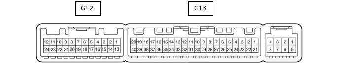
Disconnect the G13 air conditioning amplifier connector.
Measure the voltage and resistance according to the value(s) in the table below.
Terminal No. (Symbol)
Wiring Color
Terminal Description
Condition
Specified Condition
G13-21 (B) - G13-14 (GND)
V - W-B
Battery power source
Always
11 to 14 V
G13-1 (IG+) - G13-14 (GND)
L - W-B
Ignition power supply
Engine switch on (IG)
11 to 14 V
G13-1 (IG+) - G13-14 (GND)
L - W-B
Ignition power supply
Engine switch off
Below 1 V
G13-14 (GND) - Body ground
W-B - Body ground
Ground
Always
Below 1 Ω
Reconnect the G13 air conditioning amplifier connector.
Measure the voltage according to the value(s) in the table below.
Terminal No. (Symbol)
Wiring Color
Terminal Description
Condition
Specified Condition
G13-38 (RDEF) - G13-14 (GND)
P - W-B
Rear defogger signal
Engine switch on (IG), defogger switch off
11 to 14 V
G13-38 (RDEF) - G13-14 (GND)
P - W-B
Rear defogger signal
Engine switch on (IG), defogger switch on
Below 1 V
CHECK MULTI-DISPLAY ASSEMBLY
CHECK MULTI-MEDIA MODULE RECEIVER ASSEMBLY (w/ Navigation System)
CHECK MULTI-MEDIA MODULE RECEIVER ASSEMBLY (w/o Navigation System)