СИСТЕМА ECD, Diagnostic DTC:P205C, P205D
| DTC Code | DTC Name |
|---|---|
| P205C | Reductant Tank Temperature Sensor Circuit Low |
| P205D | Reductant Tank Temperature Sensor Circuit High |
DESCRIPTION
Refer to DTC P202B Click here.
| DTC Detection Drive Pattern | DTC Detection Condition | Trouble Area |
|---|---|---|
| Ignition switch ON and wait for 10 seconds or more. | An open or short circuit occurs in the temperature sensor circuit for 10 seconds or more. (1 trip detection logic) |
|
| DTC Detection Drive Pattern | DTC Detection Condition | Trouble Area |
|---|---|---|
| Ignition switch ON and wait for 10 seconds or more. | An open or short circuit occurs in the temperature sensor circuit for 10 seconds or more. (1 trip detection logic) |
|
| DTC No. | Data List |
|---|---|
| P205C P205D |
Reductant Temperature |
MONITOR DESCRIPTION
The urea pump control ECU calculates the temperature of the urea solution based on the output voltage of the temperature sensor. When the temperature sensor output voltage is outside the normal range, there may be a malfunction, short or open circuit in the temperature sensor. In this case, the urea pump control ECU determines that there is a malfunction in the temperature sensor, and then illuminates the MIL and stores a DTC through the ECM.
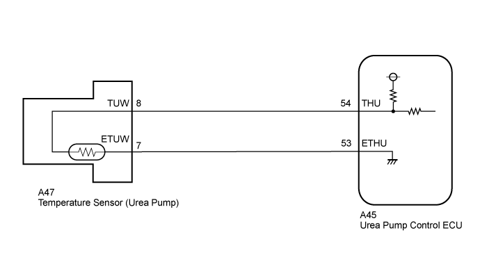
WIRING DIAGRAM
INSPECTION PROCEDURE
Tech Tips
Read freeze frame data using the GTS. Freeze frame data records the engine condition when malfunctions are detected. When troubleshooting, freeze frame data can help determine if the vehicle was moving or stationary, if the engine was warmed up or not, and other data from the time the malfunction occurred.
PROCEDURE
-
READ VALUE USING GTS
-
Connect the GTS to the DLC3.
-
Turn the ignition switch to ON and turn the GTS on.
-
Enter the following menus: Powertrain / Engine and ECT / Reductant Temperature.
-
Read the values.
Standard Reductant temperature is the same as the ambient temperature of urea tank assembly. Result Result Proceed to -40°C (-40°F) A 80°C (176°F) B Tech Tips
-
When the GTS indicates -40°C (-40°F), there is a open circuit.
-
When the GTS indicates 80°C (176°F), there is a short circuit.
-
B 
READ VALUE USING GTS (CHECK FOR SHORT IN WIRE HARNESS) Click here
A 
-
-
READ VALUE USING GTS (CHECK FOR OPEN IN WIRE HARNESS)
-
Disconnect the urea pump connector.
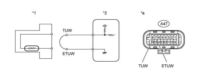
Text in Illustration *1 Temperature Sensor (Urea Pump) *2 Urea Pump Control ECU *a Front view of wire harness connector
(to Urea Pump)
- - -
Connect terminals 8 (TUW) and 7 (ETUW) of the urea pump connector on the wire harness side.
-
Connect the GTS to the DLC3.
-
Turn the ignition switch to ON and turn the GTS on.
-
Enter the following menus: Powertrain / Engine and ECT / Data List / Reductant Temperature.
-
Read the values.
OK 80°C (176°F)
NG
CHECK HARNESS AND CONNECTOR (UREA PUMP - UREA PUMP CONTROL ECU) Click here
OK
-
-
REPLACE UREA PUMP
-
Replace the urea pump Click here.
NEXT
-
-
CLEAR DTC
-
Connect the GTS to the DLC3.
-
Turn the ignition switch to ON and turn the GTS on.
-
Clear the DTCs Click here.
-
Turn the ignition switch off and wait for 30 seconds or more.
-
Read the DTCs.
NEXT
-
-
CHECK WHETHER DTC OUTPUT RECURS
-
Connect the GTS to the DLC3.
-
Turn the GTS on.
-
Turn the ignition switch to ON and wait for 10 seconds or more.
-
Enter the following menus: Powertrain / Engine and ECT / Trouble Codes.
-
Confirm that the DTCs are not output again.
NEXT 
END
-
-
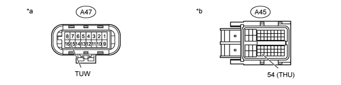
CHECK HARNESS AND CONNECTOR (UREA PUMP - UREA PUMP CONTROL ECU)
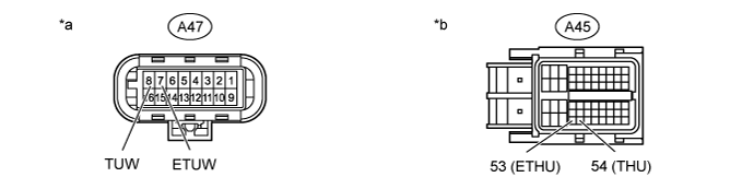
Text in Illustration *a Front view of wire harness connector
(to Urea Pump)
*b Front view of wire harness connector
(to Urea Pump Control ECU)
-
Disconnect the urea pump connector.
-
Disconnect the urea pump control ECU connector.
-
Measure the resistance according to the value(s) in the table below.
Standard Resistance: Tester Connection Condition Specified Condition A47-8 (TUW) - A45-54 (THU) Always Below 1 Ω A47-7 (ETUW) - A45-53 (ETHU) Always Below 1 Ω
NG
REPAIR OR REPLACE HARNESS OR CONNECTOR Click here
OK
-
-
REPLACE UREA PUMP CONTROL ECU
-
Replace the urea pump control ECU Click here.
NEXT
CLEAR DTC Click here
-
-
REPAIR OR REPLACE HARNESS OR CONNECTOR
-
Repair or replace the harness or connector.
NEXT
CLEAR DTC Click here
-
-
READ VALUE USING GTS (CHECK FOR SHORT IN WIRE HARNESS)
-
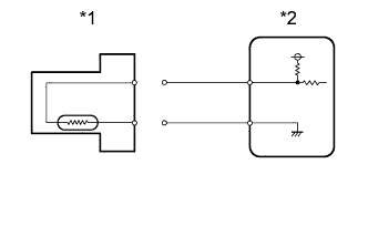
Text in Illustration *1 Temperature Sensor (Urea Pump) *2 Urea Pump Control ECU Disconnect the urea pump assembly connector.
-
Connect the GTS to the DLC3.
-
Turn the ignition switch to ON.
-
Turn the GTS on.
-
Enter the following menus: Powertrain / Engine and ECT / Data List / Reductant Temperature.
-
Read the values.
OK -40°C (-40°F)
NG
CHECK WIRE HARNESS AND CONNECTOR (UREA PUMP - UREA PUMP CONTROL ECU) Click here
OK
REPLACE UREA PUMP
-
-
CHECK WIRE HARNESS AND CONNECTOR (UREA PUMP - UREA PUMP CONTROL ECU)
Text in Illustration *a Front view of wire harness connector
(to Urea Pump)
*b Front view of wire harness connector
(to Urea Pump Control ECU)
-
Disconnect the urea pump connector.
-
Disconnect the urea pump control ECU connector.
-
Measure the resistance according to the value(s) in the table below.
Standard Resistance: Tester Connection Condition Specified Condition A47-8 (TUW) and A45-54 (THU) - Body ground and other terminals Always 10 kΩ or higher
NG
REPAIR OR REPLACE HARNESS OR CONNECTOR Click here
OK
REPLACE UREA PUMP CONTROL ECU
-