HEATER WATER PUMP(for V35A-FTS AWD) INSTALLATION
CAUTION / NOTICE / HINT
Tech Tips
-
Use the same procedure for RHD and LHD vehicles.
-
The procedure listed below is for LHD vehicles.
PROCEDURE
-
INSTALL NO. 2 WIRING AIR INDICATOR HARNESS SUB-ASSEMBLY
-
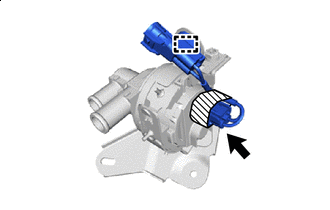

Tape Connect the connector.
-
Attach the clamp to install the No. 2 wiring air indicator harness sub-assembly.
-
-
INSTALL HEATER ACCESSORY ASSEMBLY
-
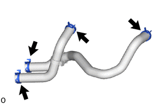
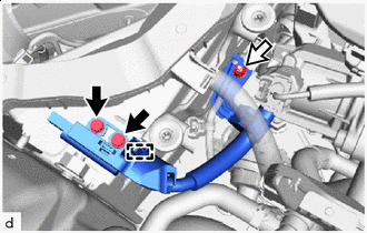
Attach the 4 hose clips to the 2 water hoses.
-
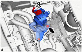

Bolt 
Nut 
Connector Install the heater accessory assembly with the bolt and nut.
- Torque:
- 8.0 N*m { 82 kgf*cm, 71 in.*lbf }
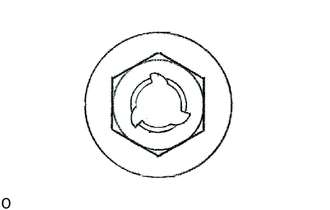
Note
If the removed nut is the same shape as that shown in the illustration, replace it the supplied replacement part.
-
Connect the connector.
-
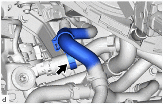
Connect 2 water hoses with its marking aligned as shown in the illustration.
Note
Do not apply excessive force to the water hose.
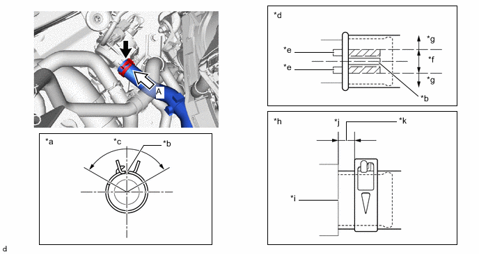
*a View A *b Water Hose Marking (Green) *c Hose Clip Installation Angle (120°) *d Water Hose Rotational Direction Aligning Position *e heater accessory assembly Rib *f OK *g NG *h Water Hose and Hose Clip Axial Direction Aligning Position *i Contact Position *j Water Hose End *k Hose Clip Installation Range (2 to 7 mm (0.0787 to 0.276 in.)) - - Water Hose Marking (Green) Maximum Leeway - - -
Connect water hose with its marking aligned as shown in the illustration.
Note
Do not apply excessive force to the water hose.
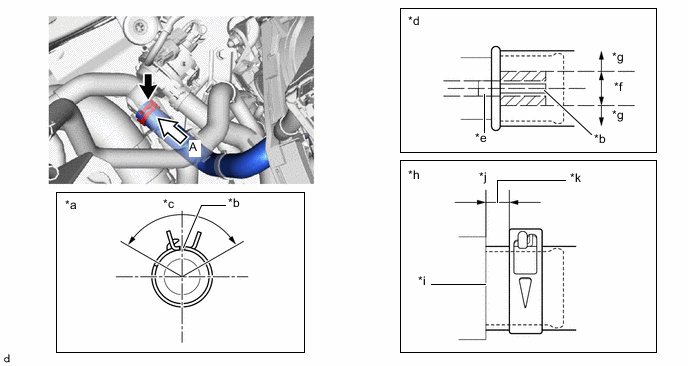
*a View A *b Water Hose Marking (White) *c Hose Clip Installation Angle (120°) *d Water Hose Rotational Direction Aligning Position *e heater accessory assembly Rib *f OK *g NG *h Water Hose and Hose Clip Axial Direction Aligning Position *i Contact Position *j Water Hose End *k Hose Clip Installation Range (2 to 7 mm (0.0787 to 0.276 in.)) - - Water Hose Marking (White) Maximum Leeway - - -
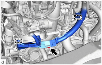
Connect water hose with its marking aligned as shown in the illustration.
Note
-
Do not apply excessive force to the water hose.
-
The installation tolerance of the water hose rotation direction is within 1 paint mark width of the nominal position.
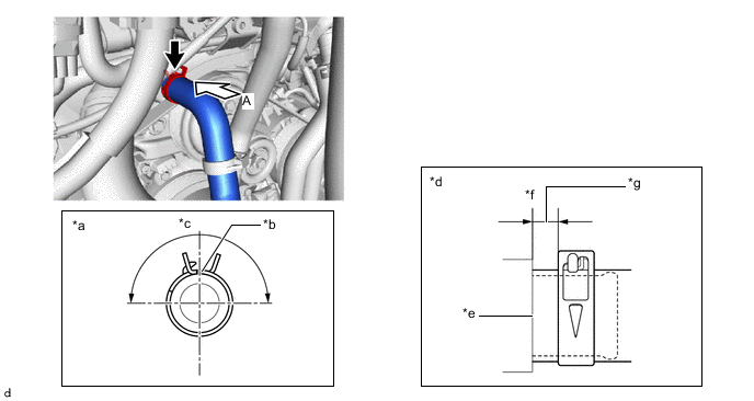
*a View A *b Water Hose Marking (Yellow) *c Hose Clip Installation Angle (180°) *d Water Hose and Hose Clip Axial Direction Aligning Position *e Contact Position *f Water Hose End *g Hose Clip Installation Range (2 to 7 mm (0.0787 to 0.276 in.)) - - Water Hose Marking (Yellow) Maximum Leeway - - -
-
Connect water hose with its marking aligned as shown in the illustration.
Note
-
Do not apply excessive force to the water hose.
-
The installation tolerance of the water hose rotation direction is within 1 paint mark width of the nominal position.
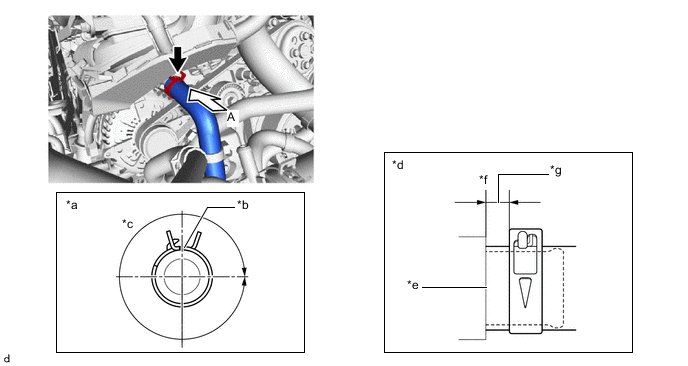
*a View A *b Water Hose Marking (Blue) *c Hose Clip Installation Angle (360°) *d Water Hose and Hose Clip Axial Direction Aligning Position *e Contact Position *f Water Hose End *g Hose Clip Installation Range (2 to 7 mm (0.0787 to 0.276 in.)) - - Water Hose Marking (Blue) Maximum Leeway - - -
-
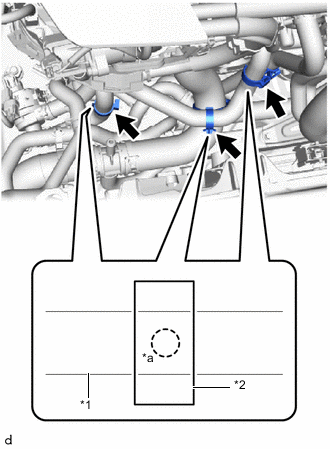
*1 Water Hose *2 Clamp *a Marking Attach the clamp.
Note
Make sure the marking is hidden in the clamp.
-
w/ In-tank Oil Cooler
-
Attach the clamp.
-
-
-
INSTALL NO. 3 ENGINE WIRE
-
Bolt Nut Attach the clamp.
-
Install the No. 3 engine wire with the bolt and nut.
Note
If the removed nut is the same shape as that shown in the illustration, replace it the supplied replacement part.
- Torque:
- Bolt
- 10 N*m { 102 kgf*cm, 7 ft.*lbf }
- Nut
- 8.0 N*m { 82 kgf*cm, 71 in.*lbf }
-
-
INSTALL ENGINE WIRE
-
Attach the clamp.
-
Install the engine wire with the bolt.
- Torque:
- 10 N*m { 102 kgf*cm, 7 ft.*lbf }
-
-
INSTALL RADIATOR RESERVE TANK ASSEMBLY
-
INSTALL AIR CLEANER WITH ELEMENT ASSEMBLY RH
-
INSTALL RADIATOR SUPPORT TO CROSSMEMBER BRACE SUB-ASSEMBLY RH
-
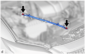
Install the radiator support to crossmember brace sub-assembly RH with the 2 bolts.
- Torque:
- 49 N*m { 500 kgf*cm, 36 ft.*lbf }
-
-
ADD ENGINE COOLANT
-
INSPECT FOR COOLANT LEAK
-
INSTALL ENGINE UNDER COVER BRACKET RH
-
CONNECT NO. 1 ENGINE UNDER COVER ASSEMBLY
-
INSTALL LOWER RADIATOR AIR DEFLECTOR
-
INSTALL UPPER RADIATOR SUPPORT SEAL
-
INSTALL RADIATOR COVER PLATE
-
INSTALL V-BANK COVER SUB-ASSEMBLY