AUTOMATIC TRANSAXLE SYSTEM Pattern Select Switch Sport Mode Circuit
| DTC Code | DTC Name |
|---|---|
| Pattern Select Switch Sport Mode Circuit |
DESCRIPTION
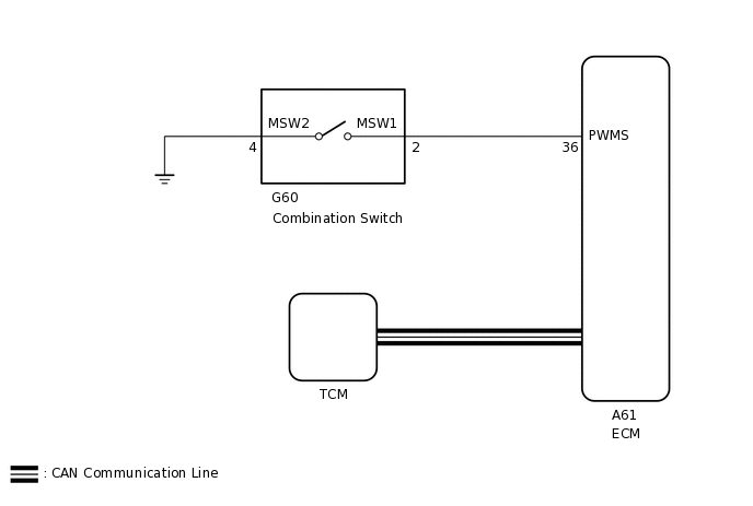
The TCM memory contains the programs for the normal and sport shift patterns.
By following the programs corresponding to the signals from the combination switch assembly, park/neutral position switch and other various sensors, the TCM switches the shift solenoid valves on and off, and controls the transaxle gear ratio.
WIRING DIAGRAM
CAUTION / NOTICE / HINT
Refer to the inspection procedure for the CAN communication system.
If the CAN communication malfunctions, the TCM cannot receive current data from the ECM. In this case, the freeze frame data output from the TCM has not been updated, so the data will not be useful for the inspection. However, reading the Data List as the first step in troubleshooting is an effective way to find malfunctions.
The malfunctioning area can be confirmed using the Bus Check function of the GTS.
for LHD with Central Gateway ECU:
for RHD with Central Gateway ECU:
Click hereClick hereClick here
for LHD without Central Gateway ECU:
for RHD without Central Gateway ECU:
PROCEDURE
INSPECT COMBINATION SWITCH ASSEMBLY
-
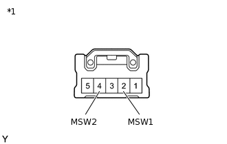
*1
Combination Switch Assembly
Remove the combination switch assembly.
Measure the resistance according to the value(s) in the table below.
Standard Resistance
Tester Connection
Switch Condition
Specified Condition
2 (MSW1) - 4 (MSW2)
Combination switch (SPORT) on
Below 1 Ω
2 (MSW1) - 4 (MSW2)
Combination switch (SPORT) off
10 kΩ or higher
Result
Proceed to
OK
NG
-
CHECK HARNESS AND CONNECTOR (COMBINATION SWITCH - BODY GROUND)
-
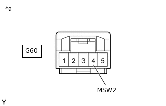
*a
Front view of wire harness connector
(to Combination Switch Assembly)
Disconnect the combination switch connector.
Measure the resistance according to the value(s) in the table below.
Standard Resistance
Tester Connection
Condition
Specified Condition
G60-4 (MSW2) - Body ground
Always
Below 1 Ω
Result
Proceed to
OK
NG
NG REPAIR OR REPLACE HARNESS OR CONNECTOR
-
CHECK HARNESS AND CONNECTOR (COMBINATION SWITCH - ECM)
-
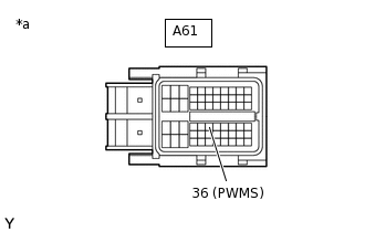
*a
Front view of wire harness connector
(to ECM)
Disconnect the ECM connector.
Measure the resistance according to the value(s) in the table below.
Standard Resistance
Tester Connection
Switch Condition
Specified Condition
A61-36 (PWMS) - Body ground
Combination switch (SPORT) on
Below 1 Ω
A61-36 (PWMS) - Body ground
Combination switch (SPORT) off
10 kΩ or higher
Result
Proceed to
OK
NG
NG REPAIR OR REPLACE HARNESS OR CONNECTOR
-