ENGINE UNIT REASSEMBLY
PROCEDURE
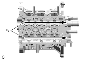
INSTALL CYLINDER BLOCK WATER JACKET SPACER
-
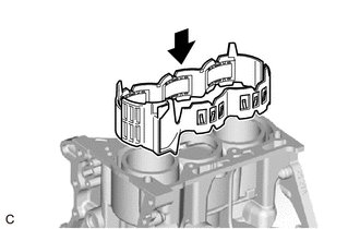
Install the cylinder block water jacket spacer LH and cylinder block water jacket spacer RH to the cylinder block sub-assembly.
-
INSTALL CYLINDER HEAD GASKET
INSTALL CYLINDER HEAD SUB-ASSEMBLY
INSTALL VALVE LIFTER
-
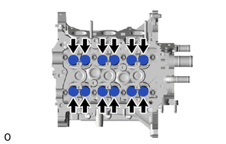
Apply engine oil to the circumference of the valve lifters.
Install the 12 valve lifters to the lifter holes.
Note:Check that the valve lifters turn smoothly after installing them.
-
INSTALL STUD BOLT
Tip:Perform this procedure only when replacement of the stud bolt is necessary.
-
Using an E6 "TORX" socket wrench, install the stud bolt to the rear engine oil seal retainer.
5.0 N*m
51 kgf*cm
44 in.*lbf
-
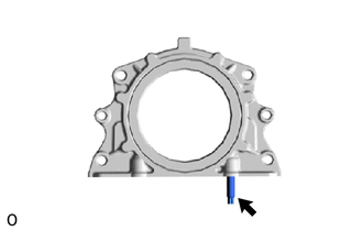
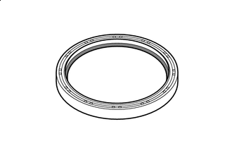
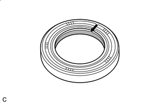
INSTALL REAR ENGINE OIL SEAL

Apply engine oil
Apply engine oil to the lip of a new rear engine oil seal.
-
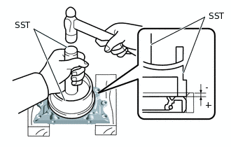
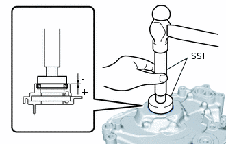
Using SST, tap in the rear engine oil seal.
09223-15020
09950-70010
09951-07200
Standard Depth
-1.0 to 0.5 mm (-0.0394 to 0.0197 in.)
Note:Keep the lip free from foreign matter.
Do not tap in the rear engine oil seal at an angle.
INSTALL REAR ENGINE OIL SEAL RETAINER
-
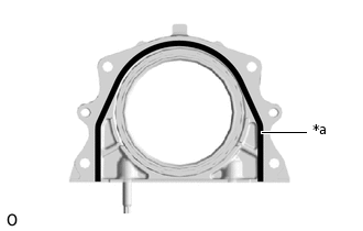
*a
Seal Packing (3.0 to 4.0 mm (0.118 to 0.157 in.))
Apply a continuous bead of seal packing to the rear engine oil seal retainer as shown in the illustration.
Seal Packing
Toyota Genuine Seal Packing Black, Three Bond 1207B or equivalent
-
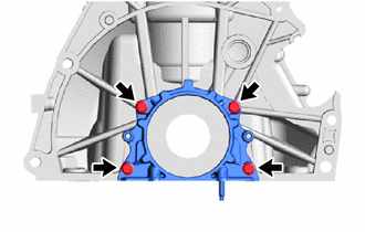
Install the rear engine oil seal retainer with the 4 bolts.
10 N*m
102 kgf*cm
7 ft.*lbf
Note:Install the rear engine oil seal retainer within 3 minutes and tighten the bolts within 15 minutes of applying seal packing.
Do not add engine oil for at least 2 hours after installation.
Do not start the engine for at least 2 hours after installation.
-
INSTALL CAMSHAFT
-
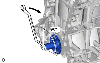

Turn
Before installing the camshaft, set the No. 1 piston to TDC/exhaust, and then turn the crankshaft approximately 90° clockwise so that a lifted valve and piston do not touch each other when the camshaft and No. 2 camshaft are installed.
-
*a
Apply engine oil
Apply engine oil to the contact areas of the cams and journals of the camshaft and No. 2 camshaft.
-
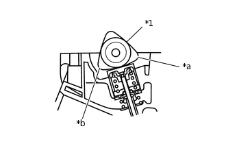
*1
Camshaft
*a
No. 1 Cylinder
*b
No. 3 Cylinder
Install the camshaft to the cylinder head sub-assembly as shown in the illustration.
-
INSTALL NO. 2 CAMSHAFT
-
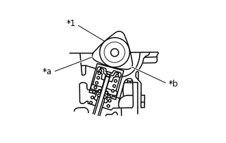
*1
No. 2 Camshaft
*a
No. 1 Cylinder
*b
No. 2 Cylinder
Install the No. 2 camshaft to the cylinder head sub-assembly as shown in the illustration.
-
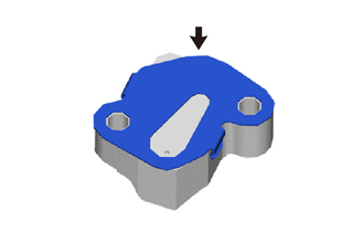
INSTALL OIL CONTROL VALVE FILTER
Install the oil control valve filter to the No. 1 camshaft bearing cap.
INSTALL CAMSHAFT BEARING CAP
-
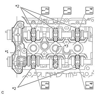
*1
No. 1 Camshaft Bearing Cap
*2
No. 2 Camshaft Bearing Cap
*3
No. 3 Camshaft Bearing Cap
Set the No. 1 camshaft bearing cap, 5 No. 2 camshaft bearing caps and No. 3 camshaft bearing cap.
Note:Install the camshaft bearing caps with the front marks facing the front of the engine.
Install the bolts to the correct positions by referring to the numbers inscribed on the bolts and the following table.
Table 1. Installation Position of No. 2 Camshaft Bearing Cap Installation Position
Inscribed No.
Intake No. 1 cylinder
I2
Intake No. 2 cylinder
I3
Intake No. 3 cylinder
I4
Exhaust No. 1 cylinder
E2
Exhaust No. 2 cylinder
-
Exhaust No. 3 cylinder
E4
-
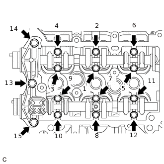
Install the 15 bolts in the order shown in the illustration.
No. 1 Camshaft Bearing Cap
15 N*m
153 kgf*cm
11 ft.*lbf
No. 2 Camshaft Bearing Cap and No. 3 Camshaft Bearing Cap
12.5 N*m
127 kgf*cm
9 ft.*lbf
-
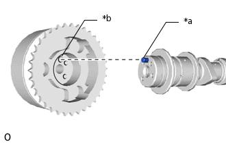
INSTALL CAMSHAFT TIMING EXHAUST GEAR ASSEMBLY
-
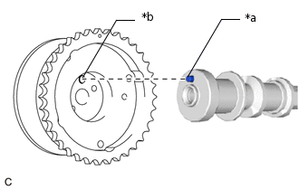
*a
Straight Pin
*b
Straight Pin Hole
Fit the camshaft timing exhaust gear assembly and No. 2 camshaft together with the straight pin and straight pin hole aligned as shown in the illustration.
-
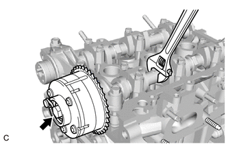
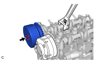
Using a wrench to hold the hexagonal portion of the No. 2 camshaft, tighten the bolt to install the camshaft timing exhaust gear assembly.
54 N*m
551 kgf*cm
40 ft.*lbf
-
INSTALL CAMSHAFT TIMING SPROCKET ASSEMBLY
-
Apply engine oil
Apply engine oil to the camshaft timing sprocket assembly installation portion of the camshaft.
-
*a
Straight Pin
*b
Straight Pin Hole
Fit the camshaft timing sprocket assembly and camshaft together with the straight pin and straight pin hole aligned as shown in the illustration.
-
Using a wrench to hold the hexagonal portion of the camshaft, tighten the bolt to install the camshaft timing sprocket assembly.
54 N*m
551 kgf*cm
40 ft.*lbf
-
INSTALL BRACKET
-
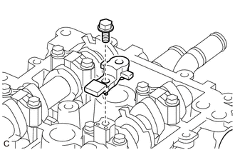
Install the bracket to the No. 3 camshaft bearing cap with the bolt.
10 N*m
102 kgf*cm
7 ft.*lbf
-
INSTALL CRANKSHAFT STRAIGHT PIN
-
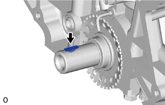
Install the crankshaft straight pin into the crankshaft groove.
-
INSTALL CRANKSHAFT TIMING SPROCKET
-
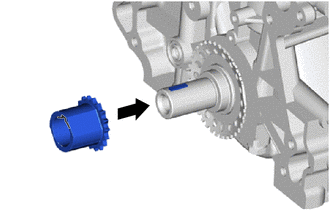
Align the groove of the crankshaft timing sprocket with the key of the crankshaft and install the crankshaft timing sprocket.
-
INSTALL TIMING CHAIN GUIDE
-
Install the timing chain guide with the 2 bolts.
9.0 N*m
92 kgf*cm
80 in.*lbf
-
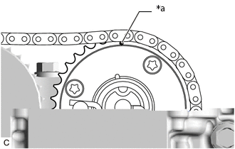
INSTALL CHAIN SUB-ASSEMBLY
-
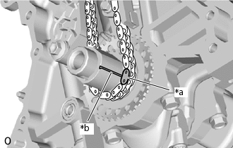
*a
Mark Plate (Yellow)
*b
Timing Mark
Align the mark plate (yellow) with the timing mark of the crankshaft timing sprocket and install the chain sub-assembly as shown in the illustration.
-
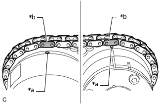
*a
Timing Mark
*b
Mark Plate (Pink)
Align the 2 mark plates (pink) with the timing marks of the camshaft timing sprocket assembly and camshaft timing exhaust gear assembly, and install the chain sub-assembly as shown in the illustration.
-
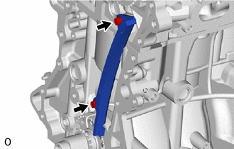
INSTALL TIMING CHAIN TENSION ARM
-
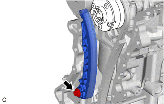
Install the timing chain tension arm with the bolt.
19 N*m
194 kgf*cm
14 ft.*lbf
-
INSTALL NO. 1 CHAIN TENSIONER ASSEMBLY
-
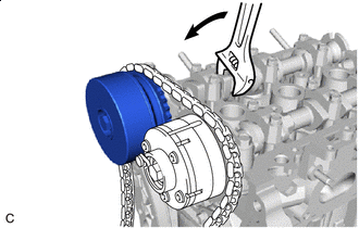
Turn
Using a wrench, slightly turn the hexagonal portion of the camshaft (intake side) counterclockwise so that there is some slack in the chain sub-assembly on the No. 1 chain tensioner assembly side.
-
Install a new chain tensioner gasket to the No. 1 chain tensioner assembly.
-
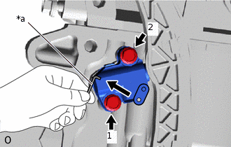
*a
Hexagon Wrench
Temporarily install the No. 1 chain tensioner assembly and chain tensioner gasket to the cylinder block sub-assembly with the 2 bolts and then tighten the 2 bolts in the order shown in the illustration.
10.5 N*m
107 kgf*cm
8 ft.*lbf
Remove the hexagon wrench, turn the crankshaft 2 complete revolutions and adjust the chain tension.
-
*a
Timing Mark
Make sure that the timing mark of the camshaft timing exhaust gear assembly is at the top with the chain sub-assembly tensioned (set No. 1 piston to TDC/ exhaust).
-
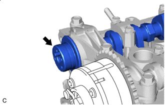
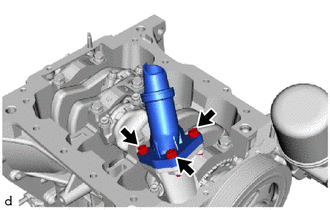
INSTALL TIMING CHAIN COVER OIL SEAL

Apply engine oil
Apply engine oil to the lip of a new timing chain cover oil seal.
-
Using SST and a hammer, tap in the timing chain cover oil seal as shown in the illustration.
09950-60010
09951-00500
09952-06010
09950-70010
09951-07200
Standard Depth
-1.0 to 0.5 mm (-0.0394 to 0.0197 in.)
Note:Do not tap in the timing chain cover oil seal at an angle.
INSTALL STUD BOLT
Tip:Perform this procedure only when replacement of the stud bolt is necessary.
-
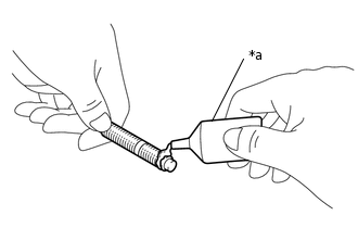
*a
Adhesive 1324
Apply adhesive to 2 or 3 threads (timing chain cover sub-assembly side) of the stud bolt.
Adhesive
Toyota Genuine Adhesive 1324, Three Bond 1324 or equivalent
-
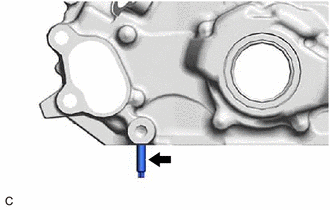
Install the stud bolt to the timing chain cover sub-assembly.
5.0 N*m
51 kgf*cm
44 in.*lbf
-
INSTALL VENTILATION CASE SUB-ASSEMBLY
-
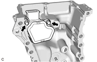
Install the ventilation case sub-assembly to the timing chain cover sub-assembly with the 2 bolts.
10 N*m
102 kgf*cm
7 ft.*lbf
-
INSTALL TIMING CHAIN COVER SUB-ASSEMBLY
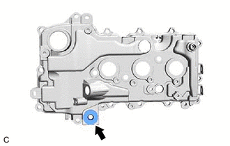
INSTALL CYLINDER BLOCK DRAIN COCK PLUG
-
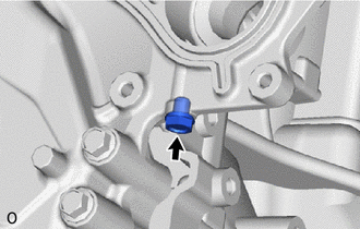
Install a new gasket and the cylinder block drain cock plug.
17.5 N*m
178 kgf*cm
13 ft.*lbf
-
INSTALL TIMING GEAR COVER TIGHT PLUG
INSTALL CRANKSHAFT PULLEY
INSTALL OIL FILTER SUB-ASSEMBLY
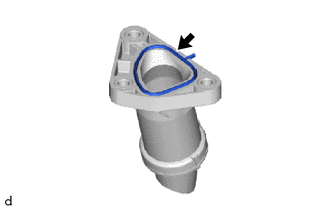
INSTALL THERMOSTAT
INSTALL WATER INLET
INSTALL OIL STRAINER SUB-ASSEMBLY
-
Install a new oil strainer gasket to the oil strainer sub-assembly.
-
Install the oil strainer sub-assembly to the timing chain cover sub-assembly with the 3 bolts.
8.5 N*m
87 kgf*cm
75 in.*lbf
-
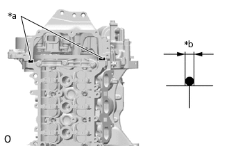
INSTALL RING PIN
Tip:Perform this procedure only when replacement of the ring pin is necessary.
-
*a
Protrusion Height
Using a plastic hammer, tap in 2 new ring pins to the specified protrusion height.
Protrusion Height
3.0 to 5.0 mm (0.118 to 0.197 in.)
-
INSTALL NO. 2 OIL PAN SUB-ASSEMBLY
-
Install the No. 2 oil pan sub-assembly to the oil pan sub-assembly with the 2 bolts.
10 N*m
102 kgf*cm
7 ft.*lbf
-
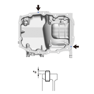
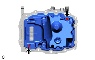
INSTALL NO. 1 OIL PAN BAFFLE PLATE
-
Temporarily install the No. 1 oil pan baffle plate to the No. 2 oil pan sub-assembly with the 4 bolts.
-
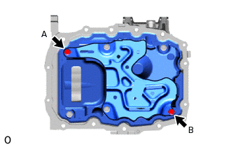
Temporarily tighten the bolt (A), then tighten the bolt (B).
10 N*m
102 kgf*cm
7 ft.*lbf
-
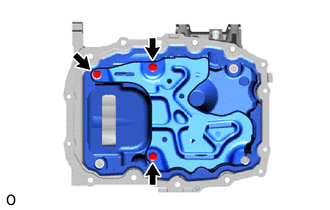
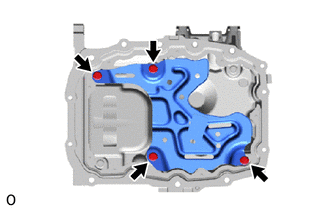
Tighten the 3 bolts.
10 N*m
102 kgf*cm
7 ft.*lbf
-
INSTALL OIL PAN SUB-ASSEMBLY
INSTALL OIL PAN DRAIN PLUG
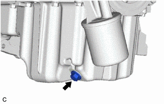
Install a new oil pan drain plug gasket and the oil pan drain plug.
29.5 N*m
301 kgf*cm
22 ft.*lbf
INSTALL GROMMET
-
Install the grommet to the cylinder head cover sub-assembly.
-
INSTALL VENTILATION SYSTEM GROMMET
INSTALL PCV VALVE (VENTILATION VALVE SUB-ASSEMBLY)
INSTALL VENTILATION HOSE
INSTALL CYLINDER HEAD COVER GASKET
-
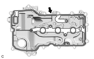
Install a new cylinder head cover gasket to the cylinder head cover sub-assembly.
-
INSTALL CYLINDER HEAD COVER SUB-ASSEMBLY
-
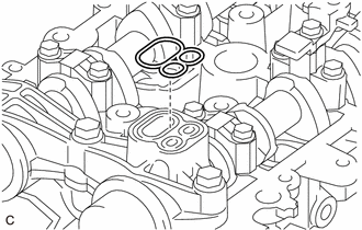
Install a new camshaft bearing cap oil hole gasket.
Clean the cylinder head cover sub-assembly, cylinder head sub-assembly and timing chain cover sub-assembly.
-
*a
Seal Packing
*b
Diameter
Apply a continuous bead of seal packing to the contact surface between the cylinder head sub-assembly and timing chain cover sub-assembly as shown in the illustration.
Seal Packing
Toyota Genuine Seal Packing Black, Three Bond 1207B or equivalent
Standard Diameter
3.0 to 4.0 mm (0.118 to 0.157 in.)
Note:Install the timing chain cover sub-assembly within 3 minutes and tighten the bolts within 10 minutes of applying seal packing.
-
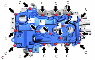
Temporarily install the cylinder head cover sub-assembly with a new bolt (A), the 2 bolts (B), 14 bolts (C) and camshaft position sensor (for Exhaust Side) (D) in the order shown in the illustration.
Bolt Length
Item
Length
Bolt (A)
30 mm (0.0984 in.)
Bolt (B)
60 mm (2.36 in.)
Bolt (C)
23.5 mm (0.925 in.)
Bolt (D)
25 mm (0.984 in.)
-
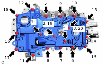
Fully tighten the 18 bolts in the order shown in the illustration.
7.7 N*m
79 kgf*cm
68 in.*lbf
-
INSTALL OIL FILLER CAP SUB-ASSEMBLY
-
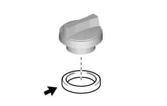
Install the oil filler cap gasket to the oil filler cap sub-assembly.
-
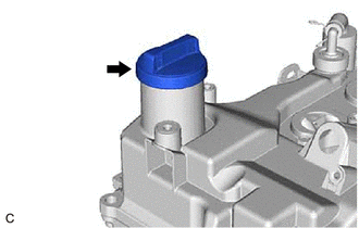
Install the oil filler cap sub-assembly.
-
INSTALL OIL CONTROL VALVE FILTER
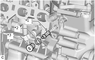
*1
Oil Control Valve Filter
*2
Gasket
*3
Head Taper Screw Plug
Install the oil control valve filter and new gasket to the head taper screw plug.
-
*a
8 mm Hexagon Socket Wrench
Using an 8 mm hexagon socket wrench, install the head taper screw plug with oil control valve filter.
24.5 N*m
250 kgf*cm
18 ft.*lbf
INSTALL KNOCK CONTROL SENSOR
INSTALL ENGINE OIL PRESSURE SWITCH ASSEMBLY
INSTALL CRANKSHAFT POSITION SENSOR
INSTALL CAMSHAFT TIMING OIL CONTROL VALVE ASSEMBLY (for Intake Side)
INSTALL CAMSHAFT TIMING OIL CONTROL VALVE ASSEMBLY (for Exhaust Side)
INSTALL ENGINE COOLANT TEMPERATURE SENSOR
INSTALL CAMSHAFT POSITION SENSOR (for Intake Side)
INSTALL SPARK PLUG
INSTALL ENGINE OIL LEVEL DIPSTICK GUIDE
Apply a small amount of engine oil to a new O-ring.
Install the O-ring to the engine oil level dipstick guide.
Install the oil level dipstick guide to the cylinder head sub-assembly and oil pan sub-assembly with the bolt.
10 N*m
102 kgf*cm
7 ft.*lbf
INSTALL ENGINE OIL LEVEL DIPSTICK
Install the oil level dipstick sub-assembly to the oil level dipstick guide.
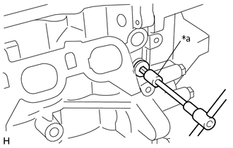
INSTALL WATER BY-PASS PIPE
-
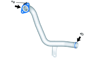
*a
Folded Tab
*b
Apply water
Install 2 new water by-pass pipe gaskets to the water by-pass pipe as shown in the illustration.
Note:Install the water by-pass pipe gasket with its folded tab towards the water by-pass pipe.
Tip:Apply water to the water by-pass pipe before installing the water by-pass gaskets to the water by-pass pipe.
-
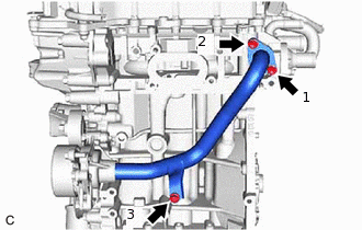
Temporarily install the water by-pass pipe with the 3 bolts.
Fully tighten the 3 bolts in the order shown in the illustration.
24 N*m
245 kgf*cm
18 ft.*lbf
-