ELECTRONICALLY CONTROLLED BRAKE SYSTEM(w/o Vacuum Brake Booster), Diagnostic DTC:C1377
| DTC Code | DTC Name |
|---|---|
| C1377 | Capacitor Malfunction |
DESCRIPTION
The brake control power supply with bracket assembly is used as auxiliary power for brake control when the battery voltage is low.
| DTC No. | Detection Item | INF Code | DTC Detection Condition | Trouble Area | Note |
|---|---|---|---|---|---|
| C1377 | Capacitor Malfunction | 101 102 103 105 106 108 109 110 |
|
|
- |
| Vehicle Condition | |||
|---|---|---|---|
| Pattern 1 | Pattern 2 | ||
| Diagnosis Condition | IG1 terminal voltage is 9.5 V or more | ○ | - |
| Malfunction Status | A malfunction signal (not communication malfunction) is received from the brake control power supply with bracket assembly | ○ | - |
| Brake control power supply with bracket assembly is deteriorated (replacement necessary). | - | ○ | |
| Detection Time | 3 seconds or more | - | |
| Number of Trips | 1 trip | 1 trip | |
| Vehicle Condition | |||
|---|---|---|---|
| Pattern 1 | Pattern 2 | ||
| Diagnosis Condition | IG1 terminal voltage is 9.5 V or more | ○ | - |
| Malfunction Status | A malfunction signal (not communication malfunction) is received from the brake control power supply with bracket assembly | ○ | - |
| Self-discharge (current leak) is excessive (internal malfunction). | - | ○ | |
| Detection Time | 3 seconds or more | - | |
| Number of Trips | 1 trip | 1 trip | |
| Vehicle Condition | |||
|---|---|---|---|
| Pattern 1 | Pattern 2 | ||
| Diagnosis Condition | IG1 terminal voltage is 9.5 V or more | ○ | - |
| Malfunction Status | A malfunction signal (not communication malfunction) is received from the brake control power supply with bracket assembly | ○ | - |
| Overvoltage (16.4 V or more) continues to be applied from the battery to the brake control power supply with bracket assembly voltage input (+BC) for 10 seconds or more. | - | ○ | |
| Detection Time | 3 seconds or more | - | |
| Number of Trips | 1 trip | 1 trip | |
| Vehicle Condition | |||
|---|---|---|---|
| Pattern 1 | Pattern 2 | ||
| Diagnosis Condition | IG1 terminal voltage is 9.5 V or more | ○ | - |
| Malfunction Status | A malfunction signal (not communication malfunction) is received from the brake control power supply with bracket assembly | ○ | - |
| Circuit inside the power back up unit (charge) is malfunctioning. | - | ○ | |
| Detection Time | 3 seconds or more | - | |
| Number of Trips | 1 trip | 1 trip | |
| Vehicle Condition | |||
|---|---|---|---|
| Pattern 1 | Pattern 2 | ||
| Diagnosis Condition | IG1 terminal voltage is 9.5 V or more | ○ | - |
| Malfunction Status | A malfunction signal (not communication malfunction) is received from the brake control power supply with bracket assembly | ○ | - |
| Circuit inside the power back up unit (back up output circuit) is malfunctioning. | - | ○ | |
| Detection Time | 3 seconds or more | - | |
| Number of Trips | 1 trip | 1 trip | |
| Vehicle Condition | |||
|---|---|---|---|
| Pattern 1 | Pattern 2 | ||
| Diagnosis Condition | IG1 terminal voltage is 9.5 V or more | ○ | - |
| Malfunction Status | A malfunction signal (not communication malfunction) is received from the brake control power supply with bracket assembly | ○ | - |
| Circuit inside the power back up unit (voltage monitor circuit) is malfunctioning. | - | ○ | |
| Detection Time | 3 seconds or more | - | |
| Number of Trips | 1 trip | 1 trip | |
| Vehicle Condition | |||
|---|---|---|---|
| Pattern 1 | Pattern 2 | ||
| Diagnosis Condition | IG1 terminal voltage is 9.5 V or more | ○ | - |
| Malfunction Status | A malfunction signal (not communication malfunction) is received from the brake control power supply with bracket assembly | ○ | - |
| Open circuit between battery (12 V) and brake control power supply with bracket assembly power input (+BC terminal). | - | ○ | |
| Detection Time | 3 seconds or more | - | |
| Number of Trips | 1 trip | 1 trip | |
| Vehicle Condition | ||||||
|---|---|---|---|---|---|---|
| Pattern 1 | Pattern 2 | Pattern 3 | Pattern 4 | Pattern 5 | ||
| Diagnosis Condition | IG1 terminal voltage is 9.5 V or more | ○ | - | - | - | - |
| Malfunction Status | A malfunction signal (not communication malfunction) is received from the brake control power supply with bracket assembly | ○ | - | - | - | - |
| Open between battery (12 V) and brake control power supply with bracket assembly output 1 (OUT1) | - | ○ | - | - | - | |
| Short circuit between battery (12 V) and brake control power supply with bracket assembly output 1 (OUT1) | - | - | ○ | - | - | |
| Open between battery (12 V) and brake control power supply with bracket assembly output 2 (OUT2) | - | - | - | ○ | - | |
| Short circuit between battery (12 V) and brake control power supply with bracket assembly output 2 (OUT2) | - | - | - | - | ○ | |
| Detection Time | 3 seconds or more | - | - | - | - | |
| Number of Trips | 1 trip | 1 trip | 1 trip | 1 trip | 1 trip | |
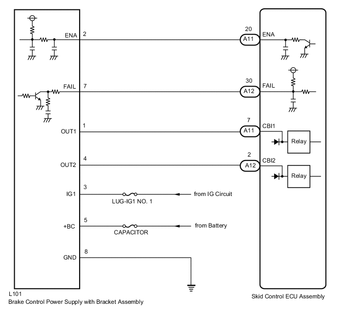
WIRING DIAGRAM
CAUTION / NOTICE / HINT
Note
-
When replacing the skid control ECU assembly, perform initialization and calibration of the linear solenoid valve.
-
Inspect the fuses for circuits related to this system before performing the following procedure.
PROCEDURE
-
CHECK FREEZE FRAME DATA
-
Check the INF code from the Freeze Frame Data stored when DTC (C1377) was stored.
Chassis > ABS/VSC/TRC > DTC(C1377) > Freeze Frame DataTester Display Detailed Freeze DTC Result Result Proceed to INF codes 109 and/or 110 are output. A INF codes 101, 102, 105, 106 and/or 108 are output. B INF code 103 is output. C
B 
REPLACE BRAKE CONTROL POWER SUPPLY WITH BRACKET ASSEMBLY Click here
C 
CHECK BATTERY Click here
A 
-
-
CHECK HARNESS AND CONNECTOR (+BC TERMINAL)
-
Make sure that there is no looseness at the locking part and the connecting part of the connector.
-
Disconnect the L101 brake control power supply with bracket assembly connector.
-
Measure the voltage according to the value(s) in the table below.
Standard Voltage Tester Connection Condition Specified Condition L101-5 (+BC) - Body ground Always 11 to 14 V Result Proceed to OK NG
NG
REPAIR OR REPLACE HARNESS OR CONNECTOR (+BC CIRCUIT)
OK
-
-
CHECK HARNESS AND CONNECTOR (GND TERMINAL)
-
Measure the resistance according to the value(s) in the table below.
Standard Resistance Tester Connection Condition Specified Condition L101-8 (GND) - Body ground Always Below 1 Ω Result Proceed to OK NG
NG
REPAIR OR REPLACE HARNESS OR CONNECTOR (GND CIRCUIT)
OK
-
-
INSPECT BRAKE CONTROL POWER SUPPLY WITH BRACKET ASSEMBLY (BRAKE CONTROL POWER SUPPLY WITH BRACKET ASSEMBLY POWER SUPPLY OUTPUT)
-
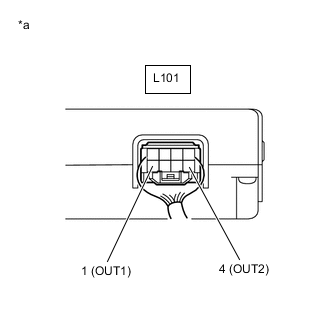
*a Component with harness connected
(Brake Control Power Supply with Bracket Assembly)
Reconnect the L101 brake control power supply with bracket assembly connector.
-
Turn the engine switch on (IG).
-
Measure the voltage according to the value(s) in the table below.
Standard Voltage Tester Connection Switch Condition Specified Condition L101-1 (OUT1) - Body ground Engine switch on (IG) 11 to 14 V L101-4 (OUT2) - Body ground Engine switch on (IG) 11 to 14 V Result Proceed to OK NG
NG
REPLACE BRAKE CONTROL POWER SUPPLY WITH BRACKET ASSEMBLY Click here
OK
-
-
INSPECT SKID CONTROL ECU ASSEMBLY (BRAKE CONTROL POWER SUPPLY WITH BRACKET ASSEMBLY POWER SUPPLY INPUT)
-
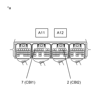
*a Component with harness connected
(Skid Control ECU Assembly)
Turn the engine switch on (IG).
-
Measure the voltage according to the value(s) in the table below.
Standard Voltage Tester Connection Switch Condition Specified Condition A11-7 (CBI1) - Body ground Engine switch on (IG) 8.8 to 14 V A12-2 (CBI2) - Body ground Engine switch on (IG) 8.8 to 14 V Result Proceed to OK NG
NG
REPLACE SKID CONTROL ECU ASSEMBLY Click here
OK
-
-
RECONFIRM DTC
-
Turn the engine switch off.
-
Clear the DTCs.
Chassis > ABS/VSC/TRC > Clear DTCs -
Turn the engine switch off.
-
Turn the engine switch on (IG).
-
Check if the same DTC is output.
Chassis > ABS/VSC/TRC > Trouble CodesResult Result Proceed to DTC C1377 is not output. A DTC C1377 is output. B
A
USE SIMULATION METHOD TO CHECK Click here
B
REPLACE SKID CONTROL ECU ASSEMBLY Click here
-
-
CHECK BATTERY
-
Check the battery voltage.
Standard Voltage Tester Connection Switch Condition Specified Condition Battery Engine switch off 11 to 14 V Result Proceed to OK NG
NG
CHARGE OR REPLACE BATTERY
OK
-
-
CHECK HARNESS AND CONNECTOR (+BC TERMINAL)
-
Make sure that there is no looseness at the locking part and the connecting part of the connector.
-
Disconnect the L101 brake control power supply with bracket assembly connector.
-
Measure the voltage according to the value(s) in the table below.
Standard Voltage Tester Connection Condition Specified Condition L101-5 (+BC) - Body ground Always 11 to 14 V Result Proceed to OK NG
NG
REPAIR OR REPLACE HARNESS OR CONNECTOR (+BC CIRCUIT)
OK
-
-
CHECK HARNESS AND CONNECTOR (GND TERMINAL)
-
Measure the resistance according to the value(s) in the table below.
Standard Resistance Tester Connection Condition Specified Condition L101-8 (GND) - Body ground Always Below 1 Ω Result Proceed to OK NG
OK
REPLACE BRAKE CONTROL POWER SUPPLY WITH BRACKET ASSEMBLY Click here
NG
REPAIR OR REPLACE HARNESS OR CONNECTOR (GND CIRCUIT)
-