AUTOMATIC TRANSMISSION SYSTEM (for 1KD-FTV), Diagnostic DTC:P0500
| DTC Code | DTC Name |
|---|---|
| P0500 | Vehicle Speed Sensor Malfunction |
DESCRIPTION
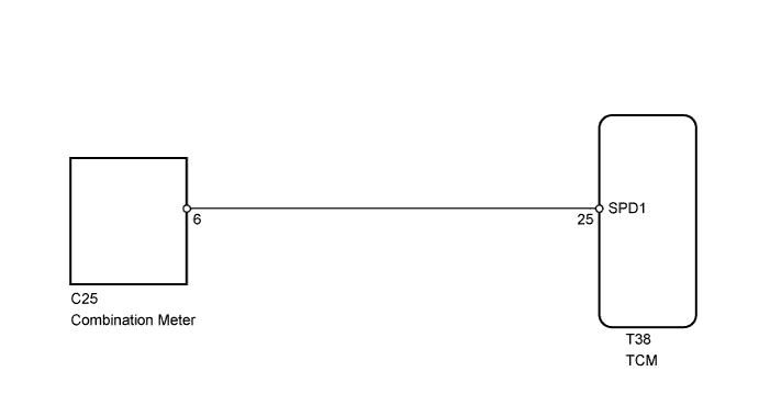
The vehicle speed sensor (SPD1) outputs a 4-pulse signal for every revolution of the rotor shaft, which is rotated by the transmission output shaft via the driven gear. After this signal is converted into a more precise rectangular waveform by the waveform shaping circuit inside the combination meter, it is then transmitted to the TCM. The TCM determines the vehicle speed based on the frequency of these pulse signals.
| DTC Code | DTC Detection Condition | Trouble Area |
|---|---|---|
| P0500 | All conditions below are detected 500 times or more continuously (2 trip detection logic): (a) No signal from vehicle speed sensor (SPD1) is input to TCM while 48 pulses of speed sensor (SP2) signal are sent (b) Vehicle speed is 9 km/h (.6 mph) or more for at least 4 seconds (c) PNP switch is off (shift lever not on P or N) (d) Transfer shift lever is not on N |
|
WIRING DIAGRAM
INSPECTION PROCEDURE
PROCEDURE
-
READ VALUE USING INTELLIGENT TESTER (VEHICLE SPEED)
-
Connect the intelligent tester to the DLC3.
-
Start the engine and turn the tester on.
-
Enter the following menus: Powertrain / ECT / Data List / Vehicle Speed.
-
Check the vehicle speed at an engine speed of 2000 rpm or more while the vehicle is running.
OK Same value as actual vehicle speed.
NG 
CHECK FOR INTERMITTENT PROBLEMS
OK 
-
-
CHECK SPEEDOMETER OPERATION
-
Check the speedometer reading in the combination meter.
Tech Tips
If the vehicle speed sensor has any malfunctions, the speedometer shows abnormal readings.
OK Speedometer operates normally.
NG
CHECK SPEEDOMETER CIRCUIT (INCLUDING SPEED SENSOR)
OK
-
-
CHECK TCM (SPD1 SIGNAL)
-
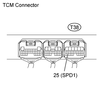
While idling, check the waveform of the TCM connector using an oscilloscope.
-
Move the shift lever to N.
-
Jack up one of the rear wheels.
-
Turn the ignition switch to ON.
-
Measure the voltage of the TCM connector as the wheel is turned slowly.
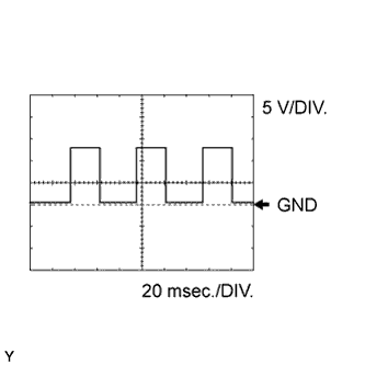
OK Refer to illustration Item Content Tester Connection T38-25 (SPD1) - Body ground Tool Setting 5 V/DIV., 20 msec./DIV. Condition Rear wheel turning slowly Tech Tips
When the wheel is turning slowly, voltage is output intermittently.
NG
REPAIR OR REPLACE HARNESS OR CONNECTOR
OK 
REPLACE TCM
-