AIR FUEL RATIO SENSOR(for Sensor 2) INSTALLATION
PROCEDURE
INSTALL AIR FUEL RATIO SENSOR
-
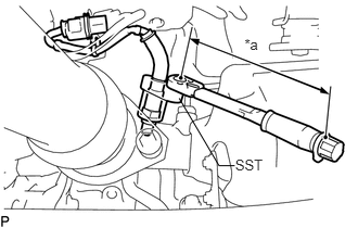
Using SST, install the air fuel ratio sensor.
09224-00011
without SST
50 N*m
510 kgf*cm
37 ft.*lbf
with SST
45 N*m
463 kgf*cm
33 ft.*lbf
Table 1. Text in Illustration *a
Fulcrum Length
Note:If an air fuel ratio sensor has been struck or dropped, replace it.
Tip:Use a torque wrench with a fulcrum length of 300 mm (11.8 in.). When using a torque wrench with a fulcrum length that is not 300 mm (11.8 in.), calculate the torque specification for the torque wrench and SST based on the "without SST" torque specification.
Make sure SST and the wrench are connected in a straight line.
Perform "Inspection After Repairs" after replacing the air fuel ratio sensor (Click here).
Attach the 2 clamps.
-
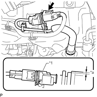
Lower the air fuel ratio sensor connector to the position shown in the illustration and connect the air fuel ratio sensor connector.
Table 2. Text in Illustration *1
Air Fuel Ratio Sensor
*2
Bracket
*a
1.5 mm (0.0591 in.) or less
-
INSPECT FOR EXHAUST GAS LEAK
INSTALL NO. 2 ENGINE UNDER COVER
PERFORM AIR FUEL RATIO SENSOR INITIALIZATION