OUTPUT SHAFT INSPECTION

PROCEDURE
-
INSPECT NO. 1 OUTPUT SHAFT
-
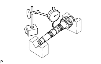
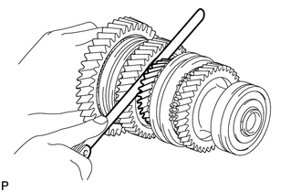
Check the No. 1 output shaft for wear and damage.
-
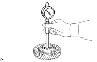
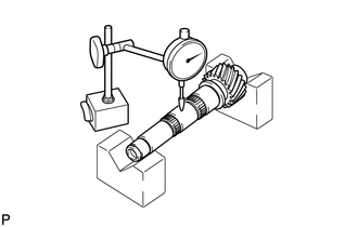
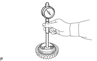
Using a dial indicator, measure the No. 1 output shaft runout.
Maximum runout 0.03 mm (0.00118 in.) If the runout is more than the maximum, replace the No. 1 output shaft.
-
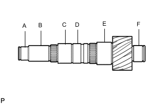
Using a micrometer, measure the outer diameter of the No. 1 output shaft journal surface.
Standard Outer Diameter Item Specified Condition A 32.002 to 32.018 mm (1.2600 to 1.2605 in.) B 35.984 to 36.000 mm (1.4167 to 1.4173 in.) C 41.984 to 42.000 mm (1.6530 to 1.6535 in.) D 41.989 to 42.000 mm (1.6532 to 1.6535 in.) E 46.984 to 47.000 mm (1.8498 to 1.8503 in.) F 36.002 to 36.018 mm (1.4174 to 1.4180 in.) If the outer diameter is less than the minimum, replace the No. 1 output shaft.
-
-
INSPECT 1ST DRIVEN GEAR THRUST CLEARANCE
-
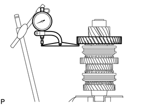
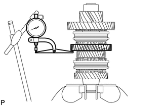
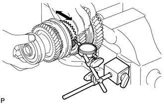
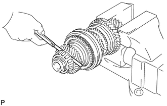
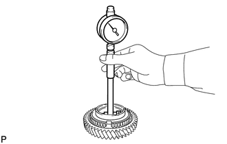
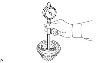
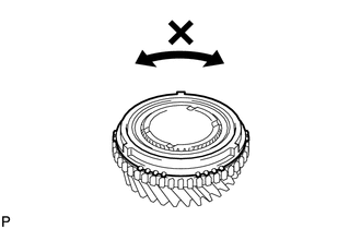
Using a dial indicator, measure the 1st driven gear thrust clearance.
Standard clearance 0.10 to 0.35 mm (0.00394 to 0.0137 in.) Maximum clearance 0.35 mm (0.0137 in.) If the clearance is more than the maximum, replace the 1st driven gear, needle roller bearing or output shaft. Replace the part or parts determined to be the most likely cause of the problem.
-
-
INSPECT 1ST DRIVEN GEAR RADIAL CLEARANCE
-
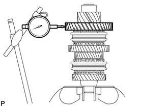
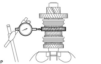
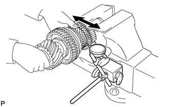
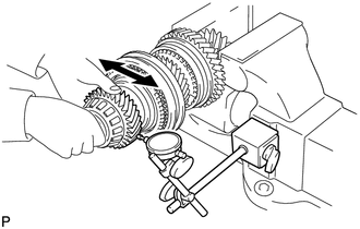
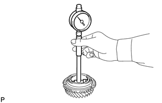
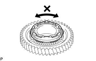
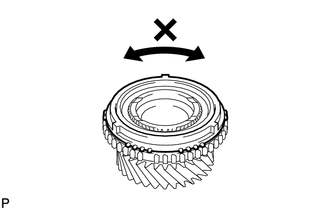
Using a dial indicator, measure the 1st driven gear radial clearance.
Standard clearance 0.015 to 0.068 mm (0.000591 to 0.00267 in.) Maximum clearance 0.068 mm (0.00267 in.) If the clearance is more than the maximum, replace the 1st driven gear, needle roller bearing or output shaft. Replace the part or parts determined to be the most likely cause of the problem.
-
-
INSPECT 2ND DRIVEN GEAR THRUST CLEARANCE
-
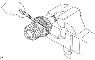
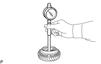
Using a dial indicator, measure the 2nd driven gear thrust clearance.
Standard clearance 0.11 to 0.46 mm (0.00434 to 0.0181 in.) Maximum clearance 0.46 mm (0.0181 in.) If the clearance is more than the maximum, replace the 2nd driven gear, needle roller bearing or output shaft. Replace the part or parts determined to be the most likely cause of the problem.
-
-
INSPECT 2ND DRIVEN GEAR RADIAL CLEARANCE
-
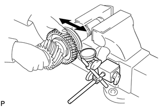
Using a dial indicator, measure the 2nd driven gear radial clearance.
Standard clearance 0.015 to 0.048 mm (0.000591 to 0.00188 in.) Maximum clearance 0.048 mm (0.00188 in.) If the clearance is more than the maximum, replace the 2nd driven gear, needle roller bearing or output shaft. Replace the part or parts determined to be the most likely cause of the problem.
-
-
INSPECT 3RD DRIVEN GEAR THRUST CLEARANCE
-
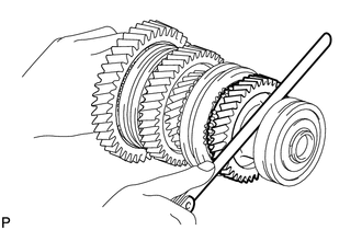
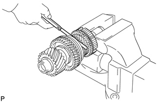
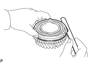
Using a feeler gauge, measure the 3rd driven gear thrust clearance.
Standard clearance 0.11 to 0.54 mm (0.00434 to 0.0212 in.) Maximum clearance 0.54 mm (0.0212 in.) If the clearance is more than the maximum, replace the 3rd driven gear, needle roller bearing or output shaft. Replace the part or parts determined to be the most likely cause of the problem.
-
-
INSPECT 3RD DRIVEN GEAR RADIAL CLEARANCE
-
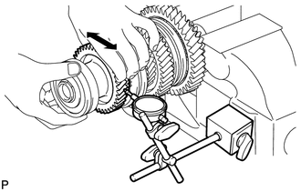
Using a dial indicator, measure the 3rd driven gear radial clearance.
Standard clearance 0.015 to 0.066 mm (0.000591 to 0.00259 in.) Maximum clearance 0.066 mm (0.00259 in.) If the clearance is more than the maximum, replace the 3rd driven gear, needle roller bearing or output shaft. Replace the part or parts determined to be the most likely cause of the problem.
-
-
INSPECT 4TH DRIVEN GEAR THRUST CLEARANCE
-
Using a feeler gauge, measure the 4th driven gear thrust clearance.
Standard clearance 0.10 to 0.65 mm (0.00394 to 0.0255 in.) Maximum clearance 0.65 mm (0.0255 in.) If the clearance is more than the maximum, replace the 4th driven gear, needle roller bearing or output shaft. Replace the part or parts determined to be the most likely cause of the problem.
-
-
INSPECT 4TH DRIVEN GEAR RADIAL CLEARANCE
-
Using a dial indicator, measure the 4th driven gear radial clearance.
Standard clearance 0.015 to 0.066 mm (0.000591 to 0.00259 in.) Maximum clearance 0.066 mm (0.00259 in.) If the clearance is more than the maximum, replace the 4th driven gear, needle roller bearing or output shaft. Replace the part or parts determined to be the most likely cause of the problem.
-
-
INSPECT 5TH DRIVEN GEAR THRUST CLEARANCE
-
Using a feeler gauge, measure the 5th driven gear thrust clearance.
Standard clearance 0.10 to 0.55 mm (0.00394 to 0.0216 in.) Maximum clearance 0.55 mm (0.0216 in.) If the clearance is more than the maximum, replace the 5th driven gear, needle roller bearing or output shaft. Replace the part or parts determined to be the most likely cause of the problem.
-
-
INSPECT 5TH DRIVEN GEAR RADIAL CLEARANCE
-
Using a dial indicator, measure the 5th driven gear radial clearance.
Standard clearance 0.015 to 0.066 mm (0.000591 to 0.00259 in.) Maximum clearance 0.066 mm (0.00259 in.) If the clearance is more than the maximum, replace the 5th driven gear, needle roller bearing or output shaft. Replace the part or parts determined to be the most likely cause of the problem.
-
-
INSPECT 6TH DRIVEN GEAR THRUST CLEARANCE
-
Using a feeler gauge, measure the 6th driven gear thrust clearance.
Standard clearance 0.10 to 0.55 mm (0.00394 to 0.0216 in.) Maximum clearance 0.55 mm (0.0216 in.) If the clearance is more than the maximum, replace the 6th driven gear, needle roller bearing or output shaft. Replace the part or parts determined to be the most likely cause of the problem.
-
-
INSPECT 6TH DRIVEN GEAR RADIAL CLEARANCE
-
Using a dial indicator, measure the 6th driven gear radial clearance.
Standard clearance 0.015 to 0.066 mm (0.000591 to 0.00259 in.) Maximum clearance 0.066 mm (0.00259 in.) If the clearance is more than the maximum, replace the 6th driven gear, needle roller bearing or output shaft. Replace the part or parts determined to be the most likely cause of the problem.
-
-
INSPECT REVERSE DRIVEN GEAR THRUST CLEARANCE
-
Using a feeler gauge, measure the reverse driven gear thrust clearance.
Standard clearance 0.11 to 0.34 mm (0.00434 to 0.0133 in.) Maximum clearance 0.34 mm (0.0133 in.) If the clearance is more than the maximum, replace the reverse driven gear, needle roller bearing or output shaft. Replace the part or parts determined to be the most likely cause of the problem.
-
-
INSPECT REVERSE DRIVEN GEAR RADIAL CLEARANCE
-
Using a dial indicator, measure the reverse driven gear radial clearance.
Standard clearance 0.015 to 0.068 mm (0.000591 to 0.00267 in.) Maximum clearance 0.068 mm (0.00267 in.) If the clearance is more than the maximum, replace the reverse driven gear, needle roller bearing or output shaft. Replace the part or parts determined to be the most likely cause of the problem.
-
-
INSPECT 1ST AND 2ND SHIFT FORK SHAFT
-
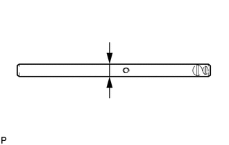
Using a micrometer, measure the 1st and 2nd shift fork shaft.
Standard outer diameter 13.982 to 14.000 mm (0.5505 to 0.5511 in.) Minimum outer diameter 13.982 mm (0.5505 in.) If the outer diameter is less than the minimum, replace the 1st and 2nd shift fork shaft.
-
-
INSPECT 3RD AND 4TH SHIFT FORK SHAFT
-
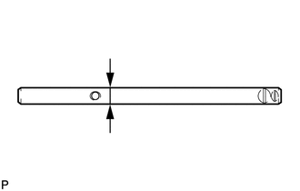
Using a micrometer, measure the 3rd and 4th shift fork shaft.
Standard outer diameter 13.982 to 14.000 mm (0.5505 to 0.5511 in.) Minimum outer diameter 13.982 mm (0.5505 in.) If the outer diameter is less than the minimum, replace the 3rd and 4th shift fork shaft.
-
-
INSPECT 5TH AND 6TH SHIFT FORK SHAFT
-
Using a micrometer, measure the 5th and 6th shift fork shaft.
Standard outer diameter 13.982 to 14.000 mm (0.5505 to 0.5511 in.) Minimum outer diameter 13.982 mm (0.5505 in.) If the outer diameter is less than the minimum, replace the 5th and 6th shift fork shaft.
-
-
INSPECT REVERSE SHIFT FORK SHAFT
-
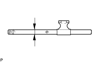
Using a micrometer, measure the reverse shift fork shaft.
Standard outer diameter 13.982 to 14.000 mm (0.5505 to 0.5511 in.) Minimum outer diameter 13.982 mm (0.5505 in.) If the outer diameter is less than the minimum, replace the reverse shift fork shaft.
-
-
INSPECT NO. 5 GEAR SHIFT FORK SHAFT
-
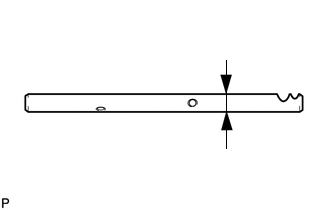
Using a micrometer, measure the No. 5 gear shift fork shaft.
Standard outer diameter 15.966 to 15.984 mm (0.6286 to 0.6292 in.) Minimum outer diameter 15.966 mm (0.6286 in.) If the outer diameter is less than the minimum, replace the No. 5 gear shift fork shaft.
-
-
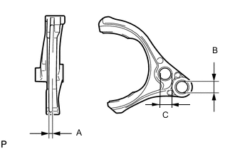
INSPECT NO. 1 GEAR SHIFT FORK
-
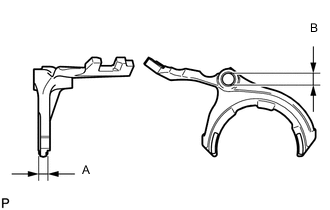
Using vernier caliper, measure the No. 1 gear shift fork.
Standard inside diameter and thickness A 9.50 to 9.80 mm (0.375 to 0.385 in.) B 14.010 to 14.043 mm (0.5516 to 0.5528 in.) If the clearance is outside the specifications, replace the No. 1 gear shift fork.
-
-
INSPECT NO. 2 GEAR SHIFT FORK
-
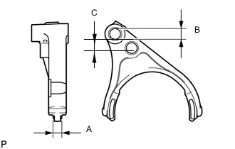
Using vernier caliper, measure the No. 2 gear shift fork.
Standard inside diameter and thickness A 9.50 to 9.80 mm (0.375 to 0.385 in.) B 14.010 to 14.043 mm (0.5516 to 0.5528 in.) C 14.70 to 15.30 mm (0.579 to 0.602 in.) If the clearance is outside the specifications, replace the No. 2 gear shift fork.
-
-
INSPECT NO. 3 GEAR SHIFT FORK
-
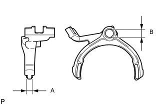
Using vernier caliper, measure the No. 3 gear shift fork.
Standard inside diameter and thickness A 9.50 to 9.80 mm (0.375 to 0.385 in.) B 14.010 to 14.043 mm (0.5516 to 0.5528 in.) If the clearance is outside the specifications, replace the No. 3 gear shift fork.
-
-
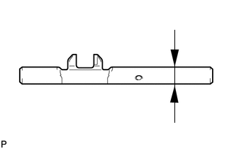
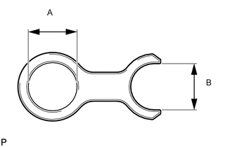
INSPECT REVERSE SHIFT FORK
-
Using vernier caliper, measure the reverse shaft fork.
Standard inside diameter and thickness A 4.40 to 4.56 mm (0.174 to 0.179 in.) B 14.010 to 14.043 mm (0.5516 to 0.5528 in.) C 14.70 to 15.30 mm (0.579 to 0.602 in.) If the clearance is outside the specifications, replace the reverse shaft fork.
-
-
INSPECT NO. 2 GEAR SHIFT HEAD
-
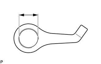
Using vernier caliper, measure the No. 2 gear shift head.
Standard inside diameter 13.994 to 14.054 mm (0.551 to 0.553 in.) Maximum inside diameter 14.054 mm (0.553 in.) If the inside diameter is more than the maximum, replace the No. 2 gear shift head.
-
-
INSPECT NO. 3 GEAR SHIFT HEAD
-
Using vernier caliper, measure the No. 3 gear shift head.
Standard inside diameter A 15.994 to 16.054 mm (0.630 to 0.632 in.) B 14.20 to 14.25 mm (0.560 to 0.561 in.) Maximum inside diameter A 16.054 mm (0.632 in.) B 14.25 mm (0.561 in.) If the inside diameter is more than the maximum, replace the No. 3 gear shift head.
-
-
INSPECT 1ST DRIVEN GEAR
-
Using a cylinder gauge, measure the inside diameter of the 1st driven gear.
Standard inside diameter 53.015 to 53.040 mm (2.0872 to 2.0881 in.) Maximum inside diameter 53.040 mm (2.0881 in.) If the inside diameter is more than the maximum, replace the 1st driven gear.
-
-
INSPECT 2ND DRIVEN GEAR
-
Using a cylinder gauge, measure the inside diameter of the 2nd driven gear.
Standard inside diameter 56.015 to 56.030 mm (2.2054 to 2.2059 in.) Maximum inside diameter 56.030 mm (2.2059 in.) If the inside diameter is more than the maximum, replace the 2nd driven gear.
-
-
INSPECT 3RD DRIVEN GEAR
-
Using a cylinder gauge, measure the inside diameter of the 3rd driven gear.
Standard inside diameter 42.015 to 42.040 mm (1.6542 to 1.6551 in.) Maximum inside diameter 42.040 mm (1.6551 in.) If the inside diameter is more than the maximum, replace the 3rd driven gear.
-
-
INSPECT 4TH DRIVEN GEAR
-
Using a cylinder gauge, measure the inside diameter of the 4th driven gear.
Standard inside diameter 48.015 to 48.040 mm (1.8904 to 1.8913 in.) Maximum inside diameter 48.040 mm (1.8913 in.) If the inside diameter is more than the maximum, replace the 4th driven gear.
-
-
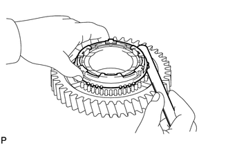
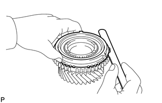
INSPECT 1ST DRIVEN GEAR SYNCHRONIZER RING SET
-
Check for wear and damage.
-
Coat the 1st driven gear cone with gear oil.
-
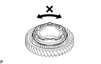
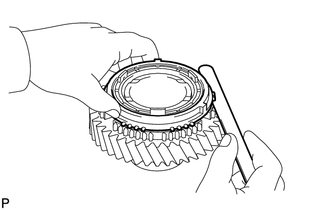
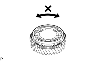
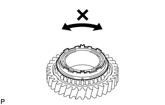
Turn the synchronizer ring in both directions while pushing it against the 1st driven gear cone and check that it locks in both directions.
If the synchronizer ring does not lock, replace the synchronizer ring.
-
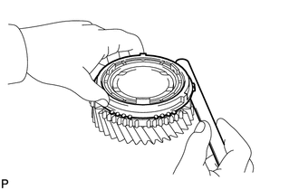
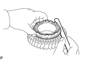
Using a feeler gauge, measure the clearance between the synchronizer ring back and gear spline end.
Standard clearance 0.98 to 1.82 mm (0.0386 to 0.0716 in.) Minimum clearance 0.98 mm (0.0386 in.) If the clearance is less than the minimum, replace the 1st driven gear synchronizer ring set.
-
-
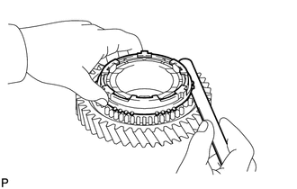
INSPECT 2ND DRIVEN GEAR SYNCHRONIZER RING SET
-
Check for wear and damage.
-
Coat the 2nd driven gear cone with gear oil.
-
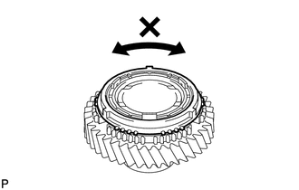
Turn the synchronizer ring in both directions while pushing it against the 2nd driven gear cone and check that it locks in both directions.
If the synchronizer ring does not lock, replace the synchronizer ring.
-
Using a feeler gauge, measure the clearance between the synchronizer ring back and 2nd gear spline end.
Standard clearance 1.08 to 1.92 mm (0.0426 to 0.0755 in.) Minimum clearance 1.08 mm (0.0426 in.) If the clearance is less than the minimum, replace the 2nd driven gear synchronizer ring set.
-
-
INSPECT 3RD DRIVEN GEAR SYNCHRONIZER RING SET
-
Check for wear and damage.
-
Coat the 3rd driven gear cone with gear oil.
-
Turn the synchronizer ring in both directions while pushing it against the 3rd driven gear cone and check that it locks in both directions.
If the synchronizer ring does not lock, replace the synchronizer ring.
-
Using a feeler gauge, measure the clearance between the 3rd gear synchronizer ring back and spline end.
Standard clearance 1.00 to 2.00 mm (0.0394 to 0.0787 in.) Minimum clearance 1.00 mm (0.0394 in.) If the clearance is less than the minimum, replace the 3rd driven gear synchronizer ring.
-
-
INSPECT 4TH DRIVEN GEAR SYNCHRONIZER RING SET
-
Check for wear and damage.
-
Coat the 4th driven gear cone with gear oil.
-
Turn the synchronizer ring in both directions while pushing it against the 4th driven gear cone and check that it locks in both directions.
If the synchronizer ring does not lock, replace the synchronizer ring.
-
Using a feeler gauge, measure the clearance between the 4th gear synchronizer ring back and spline end.
Standard clearance 0.92 to 1.88 mm (0.0363 to 0.0740 in.) Minimum clearance 0.92 mm (0.0363 in.) If the clearance is less than the minimum, replace the 4th driven gear synchronizer ring.
-
-
INSPECT NO. 1 TRANSMISSION HUB SLEEVE
-
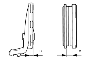
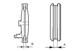
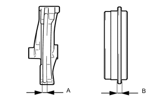
Using vernier caliper, measure the clearance between the No. 1 transmission hub sleeve and the No. 1 gear shift fork.
Standard clearance (A - B) 0.10 to 0.50 mm (0.00394 to 0.0196 in.) If the clearance is more than standard, replace the No. 1 transmission hub sleeve and No. 1 gear shift fork.
-
-
INSPECT NO. 2 TRANSMISSION HUB SLEEVE
-
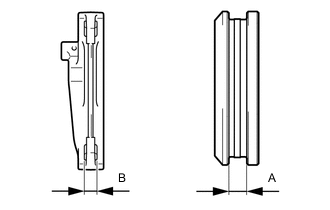
Using vernier caliper, measure the clearance between the No. 2 transmission hub sleeve and the No. 2 gear shift fork.
Standard clearance (A - B) 0.10 to 0.50 mm (0.00394 to 0.0196 in.) If the clearance is more than standard, replace the No. 2 transmission hub sleeve and No. 2 gear shift fork.
-
-
INSPECT NO. 2 OUTPUT SHAFT
-
Check the No. 2 output shaft for wear and damage.
-
Using a dial indicator, check the No. 2 output shaft runout.
Maximum runout 0.03 mm (0.00118 in.) If the runout is more than the maximum, replace the No. 2 output shaft.
-
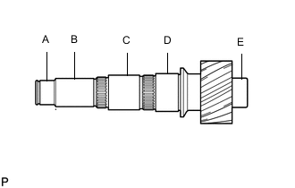
Using a micrometer, measure the outer diameter of the No. 2 output shaft journal surface.
Standard Outer Diameter Item Specified Condition A 32.002 to 32.018 mm (1.2600 to 1.2605 in.) B 35.984 to 36.000 mm (1.4167 to 1.4173 in.) C 41.984 to 42.000 mm (1.6530 to 1.6535 in.) D 46.984 to 47.000 mm (1.8498 to 1.8503 in.) E 35.002 to 35.018 mm (1.3781 to 1.3786 in.) If the outer diameter is less than the standard, replace the No. 2 output shaft.
-
-
INSPECT 5TH DRIVEN GEAR
-

Using a cylinder gauge, measure the inside diameter of the 5th driven gear.
Standard inside diameter 48.015 to 48.040 mm (1.890 to 1.891 in.) Maximum inside diameter 48.040 mm (1.891 in.) If the inside diameter is more than the maximum, replace the 5th driven gear.
-
-
INSPECT 6TH DRIVEN GEAR
-
Using a cylinder gauge, measure the inside diameter of the 6th driven gear.
Standard inside diameter 42.015 to 42.040 mm (1.654 to 1.655 in.) Maximum inside diameter 42.040 mm (1.655 in.) If the inside diameter is more than the maximum, replace the 6th driven gear.
-
-
INSPECT REVERSE DRIVEN GEAR
-
Using a cylinder gauge, measure the inside diameter of the reverse driven gear.
Standard inside diameter 53.015 to 53.040 mm (2.0873 to 2.0881 in.) Maximum inside diameter 53.040 mm (2.0881 in.) If the inside diameter is more than the maximum, replace the reverse driven gear.
-
-
INSPECT 5TH DRIVEN SYNCHRONIZER RING SET
-
Check for wear and damage.
-
Coat the 5th driven gear cone with gear oil.
-
Turn the synchronizer ring in both directions while pushing it against the 5th driven gear cone and check that it locks in both directions.
If the synchronizer ring does not lock, replace the synchronizer ring.
-
Using a feeler gauge, measure the clearance between the synchronizer ring back and 5th driven gear spline end.
Standard clearance 0.80 to 1.60 mm (0.0315 to 0.0629 in.) Minimum clearance 0.80 mm (0.0315 in.) If the clearance is less than the minimum, replace the 5th driven gear synchronizer ring.
-
-
INSPECT 6TH DRIVEN SYNCHRONIZER RING SET
-
Check for wear and damage.
-
Coat the 6th driven gear cone with gear oil.
-
Turn the synchronizer ring in both directions while pushing it against the 6th driven gear cone and check that it locks in both directions.
If the synchronizer ring does not lock, replace the synchronizer ring.
-
Using a feeler gauge, measure the clearance between the gear synchronizer ring back and 6th driven gear spline end.
Standard clearance 0.80 to 1.60 mm (0.0315 to 0.0629 in.) Minimum clearance 0.80 mm (0.0315 in.) If the clearance is less than the minimum, replace the 6th driven gear synchronizer ring.
-
-
INSPECT REVERSE DRIVEN SYNCHRONIZER RING SET
-
Check for wear and damage.
-
Coat the reverse driven gear cone with gear oil.
-
Turn the synchronizer ring in both directions while pushing it against the reverse driven gear cone and check that it locks in both directions.
If the synchronizer ring does not lock, replace the synchronizer ring.
-
Using a feeler gauge, measure the clearance between the synchronizer ring back and reverse driven gear spline end.
Standard clearance 0.68 to 1.32 mm (0.0268 to 0.0519 in.) Minimum clearance 0.68 mm (0.0268 in.) If the clearance is less than the minimum, replace the reverse driven gear synchronizer ring.
-
-
INSPECT NO. 3 TRANSMISSION HUB SLEEVE
-
Using vernier caliper, measure the clearance between the No. 3 transmission hub sleeve and the No. 3 gear shift fork.
Standard clearance (A - B) 0.10 to 0.50 mm (0.00394 to 0.0196 in.) If the clearance is more than the standard, replace the No. 3 transmission hub sleeve and No. 3 gear shift fork.
-
-
INSPECT NO. 4 TRANSMISSION HUB SLEEVE
-
Using vernier caliper, measure the clearance between the No. 4 transmission hub sleeve and the reverse shift fork.
Standard clearance (A - B) 0.15 to 0.41 mm (0.00591 to 0.0161 in.) If the clearance is more than standard, replace the No. 4 transmission hub sleeve and reverse shift fork.
-