BATTERY CURRENT SENSOR INSPECTION
PROCEDURE
CHECK BATTERY CURRENT SENSOR ASSEMBLY
Check the battery current sensor assembly.
-
Measure the resistance according to the value(s) in the table below.
Standard Resistance
Tester Connection
Condition
Specified Condition
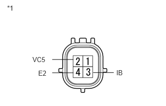
2 (VC5) - 4 (E2)
Always
0.1 to 10 kΩ
2 (VC5) - 3 (IB)
Always
Below 0.5 kΩ
3 (IB) - 4 (E2)
Always
0.05 to 10 kΩ
Table 1. Text in Illustration *1
Component without harness connected
(Battery Current Sensor)
If the result is not as specified, replace the sensor assembly.
-
Check the battery temperature sensor.
-
Measure the resistance according to the value(s) in the table below.
Standard Resistance
Tester Connection
Condition
Specified Condition
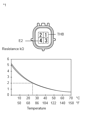
1 (THB) - 4 (E2)
20 to 30°C (68 to 86°F)
1.5 to 2.5 kΩ
Table 2. Text in Illustration *1
Component without harness connected
(Battery Current Sensor)
Note:As the temperature increases, the resistance decreases (See graph).
The battery temperature sensor is part of the battery current sensor.
If the result is not as specified, replace the sensor assembly.
-