NAVIGATION SYSTEM, Diagnostic DTC:B15C0, B15C1
| DTC Code | DTC Name |
|---|---|
| B15C0 | GPS Antenna Connection Malfunction(short) |
| B15C1 | GPS Antenna Connection Malfunction(break) |
DESCRIPTION
These DTCs are stored when a malfunction occurs in the navigation antenna assembly*2 or antenna divider*1.
| DTC No. | Detection Item | DTC Detection Condition | Trouble Area |
|---|---|---|---|
| B15C0 | GPS Antenna Connection Malfunction(short) |
|
|
| B15C1 | GPS Antenna Connection Malfunction(break) |
|
|
-
*1: w/ Telematics Transceiver
-
*2: w/o Telematics Transceiver
WIRING DIAGRAM
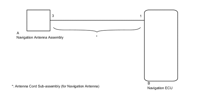
Figure 1. w/ Telematics Transceiver
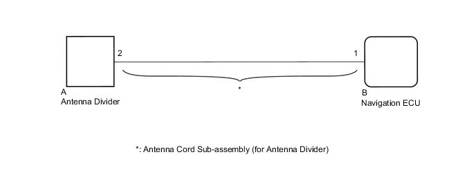
Figure 2. w/o Telematics Transceiver
CAUTION / NOTICE / HINT
Note
-
When replacing the navigation ECU, always replace it with a new one. If a navigation ECU which was installed to another vehicle is used, the following may occur:
-
A communication malfunction DTC may be stored.
-
The navigation ECU may not operate normally.
-
Check that the antenna cord sub-assembly (for navigation antenna)*1 or antenna cord sub-assembly (for antenna divider)*2 is properly installed and does not have any sharp bends, pinching or loose connections before performing following procedure.
*1: w/o Telematics Transceiver
*2: w/ Telematics Transceiver
PROCEDURE
-
CHECK DTC
-
Clear the DTCs.
Body Electrical > Navigation System > Clear DTCs -
Recheck for DTCs and check that no DTCs are output.
Body Electrical > Navigation System > Trouble CodesOK No DTCs are output. Result Result Proceed to OK A NG (w/o Telematics Transceiver) B NG (w/ Telematics Transceiver) C
A 
USE SIMULATION METHOD TO CHECK Click here
C 
INSPECT ANTENNA DIVIDER Click here
B 
-
-
INSPECT ANTENNA CORD SUB-ASSEMBLY (for Navigation Antenna)
-
Remove the antenna cord sub-assembly (for navigation antenna).
-
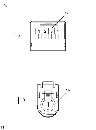
*a Component without harness connected
(Antenna Cord Sub-assembly (for Navigation Antenna))
Measure the resistance according to the value(s) in the table below.
Standard Resistance Tester Connection Condition Specified Condition A-3 - B-1 Always Below 1 Ω A-3a - B-1a Always Below 1 Ω A-3 or B-1 - Body ground Always 10 kΩ or higher Result Proceed to OK NG
NG
REPLACE ANTENNA CORD SUB-ASSEMBLY (for Navigation Antenna) Click here
OK
-
-
INSPECT NAVIGATION ANTENNA ASSEMBLY
-
Remove the navigation antenna assembly.
-
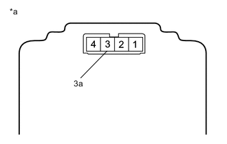
*a Component without harness connected
(Navigation Antenna Assembly)
Measure the resistance according to the value(s) in the table below.
Standard Resistance Tester Connection Condition Specified Condition 3 - 3a Always 50 to 500 Ω Result Proceed to OK NG
OK
REPLACE NAVIGATION ECU Click here
NG
REPLACE NAVIGATION ANTENNA ASSEMBLY Click here
-
-
INSPECT ANTENNA DIVIDER
-
Remove the antenna divider.
-
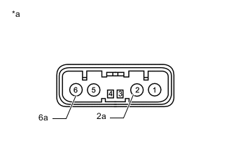
*a Component without harness connected
(Antenna Divider)
Measure the resistance according to the value(s) in the table below.
Standard Resistance Tester Connection Condition Specified Condition 2 - 6 Always 10 kΩ or higher 2 - 2a Always 243 to 267 Ω 6 - 6a Always 10 kΩ or higher Result Proceed to OK NG
NG
REPLACE ANTENNA DIVIDER Click here
OK
-
-
INSPECT ANTENNA CORD SUB-ASSEMBLY (for Antenna Divider)
-
Remove the antenna cord sub-assembly (for antenna divider).
-
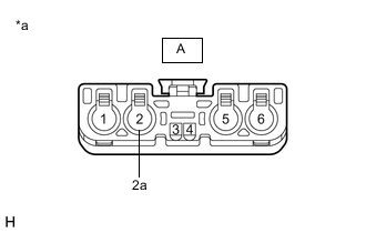
*a Component without harness connected
(Antenna Cord Sub-assembly (for Antenna Divider))

*a Component without harness connected
(Antenna Cord Sub-assembly (for Antenna Divider))
Measure the resistance according to the value(s) in the table below.
Standard Resistance Tester Connection Condition Specified Condition A-2 - B-1 Always Below 1 Ω A-2a - B-1a Always Below 1 Ω A-2 or B-1 - Body ground Always 10 kΩ or higher A-2a or B-1a - Body ground Always 10 kΩ or higher Result Proceed to OK NG
NG
REPLACE ANTENNA CORD SUB-ASSEMBLY (for Antenna Divider) Click here
OK
-
-
REPLACE ANTENNA DIVIDER
-
Replace the antenna divider with a new or known good one.
-
Clear the DTCs.
Body Electrical > Navigation System > Clear DTCs -
Recheck for DTCs and check that no DTCs are output.
Body Electrical > Navigation System > Trouble CodesOK No DTCs are output. Result Proceed to OK NG
OK
END
NG
REPLACE NAVIGATION ECU Click here
-