CAN COMMUNICATION SYSTEM TERMINALS OF ECU
Operating the engine switch, any switches or any doors triggers related ECU and sensor communication with the CAN, which causes resistance variation.
DISCONNECT CABLE FROM NEGATIVE BATTERY TERMINAL
Disconnect the cable from the negative (-) battery terminal before measuring the resistances of the main wire and the branch wire.
CAUTION:Wait at least 90 seconds after disconnecting the cable from the negative (-) battery terminal to disable the SRS system (Click here).
Note:Before measuring the resistance, leave the vehicle for at least 1 minute and do not operate the engine switch, any switches or any doors. If doors need to be opened in order to check connectors, open the doors and leave them open.
After turning the engine switch off, waiting time may be required before disconnecting the cable from the battery terminal. Therefore, make sure to read the disconnecting the cable from the battery terminal notice before proceeding with work (Click hereClick here).
When disconnecting the cable, some systems need to be initialized after the cable is reconnected (Click hereClick hereClick here).
JUNCTION CONNECTOR
NO. 1 JUNCTION CONNECTOR
G82 No. 1 junction connector
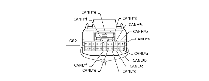
*a
for No. 2 Junction Connector
*b
for Four Wheel Drive Control ECU
*c
for Certification ECU (Smart Key ECU Assembly)
*d
for Power Management Control ECU (V1 Bus)
*e
for DCM (Telematics Transceiver) (w/ Emergency Call Switch)
*f
for ECM (V1 Bus)
No. 1 Junction Connector
Wiring Color
Connect to
G82-1 (CANH)
GR
No. 2 junction connector
G82-12 (CANL)
W
G82-2 (CANH)
G
Four wheel drive control ECU
G82-13 (CANL)
W
G82-3 (CANH)
P
Certification ECU (smart key ECU assembly)
G82-14 (CANL)
W
G82-4 (CANH)
BR
Power management control ECU (V1 bus)
G82-15 (CANL)
W
G82-5 (CANH)
V
DCM (telematics transceiver)*
G82-16 (CANL)
W
G82-6 (CANH)
R
ECM (V1 bus)
G82-17 (CANL)
W
*: w/ Emergency Call Switch
G83 No. 1 junction connector
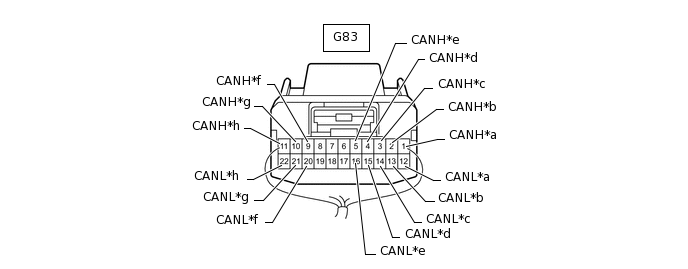
*a
for No. 3 Junction Connector (V2 Bus)
*b
for Power Management Control ECU (V2 Bus)
*c
for Parking Assist ECU (w/ Side Monitor System)
*d
for Driving Support ECU Assembly (w/ Pre-crash Safety System) (V2 Bus)
*e
for Clearance Warning ECU Assembly (w/ LEXUS Parking Assist-sensor System)
*f
for ECM (Power Management Bus)
*g
for Air Conditioning Amplifier Assembly
*h
for Power Management Control ECU (Power Management Bus)
No. 1 Junction Connector
Wiring Color
Connect to
G83-1 (CANH)
P
No. 3 junction connector (V2 bus)
G83-12 (CANL)
W
G83-2 (CANH)
V
Power management control ECU (V2 bus)
G83-13 (CANL)
W
G83-3 (CANH)
B
Parking assist ECU*1
G83-14 (CANL)
W
G83-4 (CANH)
G
Driving support ECU assembly*2 (V2 bus)
G83-15 (CANL)
W
G83-5 (CANH)
GR
Clearance warning ECU assembly*3
G83-16 (CANL)
W
G83-9 (CANH)
BR
ECM (power management bus)
G83-20 (CANL)
GR
G83-10 (CANH)
BR
Air conditioning amplifier assembly
G83-21 (CANL)
Y
G83-11 (CANH)
BR
Power management control ECU (power management bus)
G83-22 (CANL)
W
*1: w/ Side Monitor System
*2: w/ Pre-crash Safety System
*3: w/ LEXUS Parking Assist-sensor System
G84 No. 1 junction connector
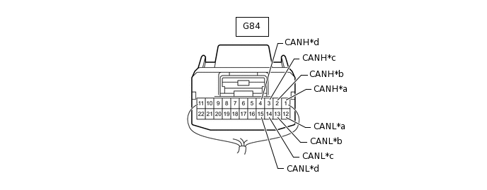
*a
for Outer Mirror Control ECU Assembly RH
*b
for Driving Support Switch Control ECU
*c
for No. 6 Junction Connector
*d
for No. 3 Junction Connector (MS Bus)
No. 1 Junction Connector
Wiring Color
Connect to
G84-1 (CANH)
G
Outer mirror control ECU assembly RH
G84-12 (CANL)
W
G84-2 (CANH)
R
Driving support switch control ECU
G84-13 (CANL)
W
G84-3 (CANH)
LG
No. 6 junction connector
G84-14 (CANL)
W
G84-4 (CANH)
V
No. 3 junction connector (MS bus)
G84-15 (CANL)
W
NO. 2 JUNCTION CONNECTOR
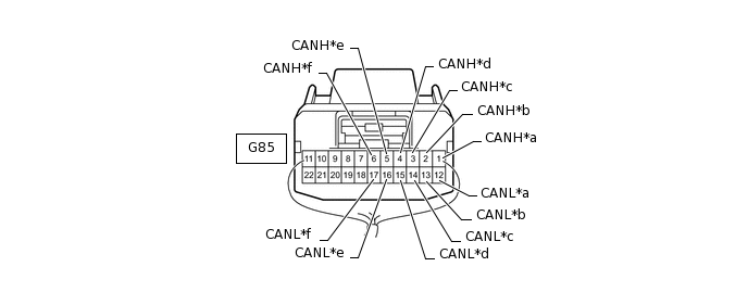
*a
for No. 1 Junction Connector (V1 Bus)
*b
for Multi-media Module Receiver Assembly
*c
for Spiral with Sensor Cable Sub-assembly (Steering Angle Sensor)
*d
for Yaw Rate Sensor Assembly
*e
for Center Airbag Sensor Assembly
*f
for No. 3 Junction Connector (V1 Bus)
No. 2 Junction Connector
Wiring Color
Connect to
G85-1 (CANH)
GR
No. 1 junction connector (V1 bus)
G85-12 (CANL)
W
G85-2 (CANH)
P
Multi-media module receiver assembly
G85-13 (CANL)
W
G85-3 (CANH)
G
Spiral with sensor cable sub-assembly (steering angle sensor)
G85-14 (CANL)
W
G85-4 (CANH)
R
Yaw rate sensor assembly
G85-15 (CANL)
W
G85-5 (CANH)
Y
Center airbag sensor assembly
G85-16 (CANL)
W
G85-6 (CANH)
LG
No. 3 junction connector (V1 bus)
G85-17 (CANL)
W
NO. 3 JUNCTION CONNECTOR
G79 No. 3 junction connector
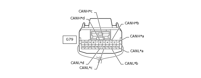
*a
for No. 2 Junction Connector
*b
for Main Body ECU (Multiplex Network Body ECU) (V1 Bus)
*c
for DLC3
*d
for No. 4 Junction Connector (V1 Bus)
No. 3 Junction Connector
Wiring Color
Connect to
G79-1 (CANH)
LG
No. 2 junction connector
G79-12 (CANL)
W
G79-3 (CANH)
L
Main body ECU (multiplex network body ECU) (V1 bus)
G79-14 (CANL)
W
G79-5 (CANH)
R
DLC3
G79-16 (CANL)
W
G79-6 (CANH)
B
No. 4 junction connector (V1 Bus)
G79-17 (CANL)
W
G80 No. 3 junction connector
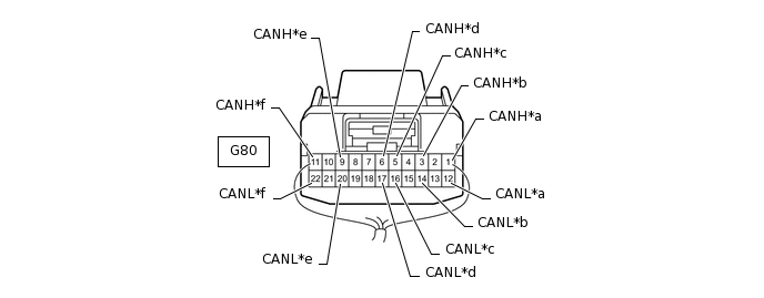
*a
for No. 1 Junction Connector (V2 Bus)
*b
for No. 7 Junction Connector (w/ Blind Spot Monitor System)
for No. 4 Junction Connector (w/o Blind Spot Monitor System) (V2 Bus)
*c
for Stabilizer Control ECU
*d
for Seat Belt Control ECU (w/ Pre-crash Safety System)
*e
for Driving Support ECU Assembly (w/ Pre-crash Safety System) (Sensor Bus)
*f
for Millimeter Wave Radar Sensor Assembly (w/ Pre-crash Safety System)
No. 3 Junction Connector
Wiring Color
Connect to
G80-1 (CANH)
P
No. 1 junction connector (V2 bus)
G80-12 (CANL)
W
G80-3 (CANH)
B
for No. 7 junction connector*1
for No. 4 junction connector*2 (V2 Bus)
G80-14 (CANL)
W
G80-5 (CANH)
V
Stabilizer control ECU
G80-16 (CANL)
W
G80-6 (CANH)
L
Seat belt control ECU*3
G80-17 (CANL)
W
G80-9 (CANH)
L
Driving support ECU assembly*3 (sensor bus)
G80-20 (CANL)
W
G80-11 (CANH)
LG
Millimeter wave radar sensor assembly*3
G80-22 (CANL)
W
*1: w/ Blind Spot Monitor System
*2: w/o Blind Spot Monitor System
*3: w/ Pre-crash Safety System
G81 No. 3 junction connector
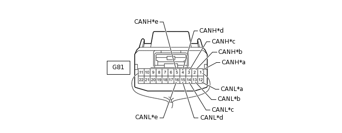
*a
for Outer Mirror Control ECU Assembly LH
*b
for Front Power Seat Switch LH
*c
for Multiplex Tilt and Telescopic ECU
*d
for Main Body ECU (Multiplex Network Body ECU) (MS Bus)
*e
for No. 1 Junction Connector (MS Bus)
-
-
No. 3 Junction Connector
Wiring Color
Connect to
G81-1 (CANH)
B
Outer mirror control ECU assembly LH
G81-12 (CANL)
W
G81-2 (CANH)
L
Front power seat switch LH
G81-13 (CANL)
W
G81-3 (CANH)
GR
Multiplex tilt and telescopic ECU
G81-14 (CANL)
W
G81-4 (CANH)
P
Main body ECU (multiplex network body ECU) (MS bus)
G81-15 (CANL)
W
G81-5 (CANH)
V
No. 1 junction connector (MS bus)
G81-16 (CANL)
W
NO. 4 JUNCTION CONNECTOR
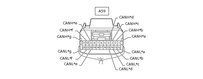
*a
for No. 5 Junction Connector
*b
for No. 7 Junction Connector (w/ Blind Spot Monitor System)
for No. 3 Junction Connector (w/o Blind Spot Monitor System) (V2 Bus)
*c
for Suspension Control ECU
*d
for Headlight Swivel ECU Assembly
*e
for No. 3 Junction Connector (V1 Bus)
*f
for Combination Meter Assembly
*g
for Master Cylinder Solenoid (Skid Control ECU)
-
-
No. 4 Junction Connector
Wiring Color
Connect to
A59-1 (CANH)
LG
No. 5 junction connector
A59-12 (CANL)
W
A59-2 (CANH)
B
No. 7 junction connector*1
No. 3 junction connector*2 (V2 bus)
A59-13 (CANL)
W
A59-3 (CANH)
GR
Suspension control ECU
A59-14 (CANL)
W
A59-4 (CANH)
V
Headlight swivel ECU assembly
A59-15 (CANL)
W
A59-9 (CANH)
R
No. 3 junction connector (V1 bus)
A59-20 (CANL)
W
A59-10 (CANH)
LG
Combination meter assembly
A59-21 (CANL)
W
A59-11 (CANH)
B
Master cylinder solenoid (skid control ECU)
A59-22 (CANL)
W
*1: w/ Blind Spot Monitor System
*2: w/o Blind Spot Monitor System
-
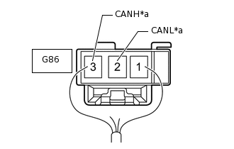
*a
for No. 4 Junction Connector (V2 Bus)
NO. 5 JUNCTION CONNECTOR
No. 5 Junction Connector
Wiring Color
Connect to
G86-2 (CANL)
W
No. 4 junction connector (V2 bus)
G86-3 (CANH)
LG
-
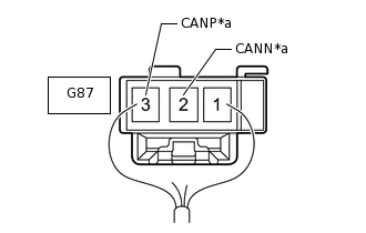
*a
for No. 1 Junction Connector (MS Bus)
NO. 6 JUNCTION CONNECTOR
No. 6 Junction Connector
Wiring Color
Connect to
G87-2 (CANN)
W
No. 1 junction connector (MS bus)
G87-3 (CANP)
LG
NO. 7 JUNCTION CONNECTOR (w/ Blind Spot Monitor System)
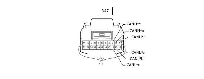
*a
for No. 3 Junction Connector (V2 Bus)
*b
for Blind Spot Monitor Sensor LH
*c
for No. 4 Junction Connector (V2 Bus)
-
-
No. 7 Junction Connector
Wiring Color
Connect to
R47-1 (CANH)
LG
No. 3 junction connector (V2 bus)
R47-12 (CANL)
W
R47-2 (CANH)
G
Blind spot monitor sensor LH
R47-13 (CANL)
W
R47-3 (CANH)
B
No. 4 junction connector (V2 bus)
R47-14 (CANL)
W
CHECK DLC3
Disconnect the cable from the negative (-) battery terminal before measuring the resistances of the main wire and the branch wire.
CAUTION:Wait at least 90 seconds after disconnecting the cable from the negative (-) battery terminal to disable the SRS system.
Note:After turning the engine switch off, waiting time may be required before disconnecting the cable from the battery terminal. Therefore, make sure to read the disconnecting the cable from the battery terminal notice before proceeding with work (Click hereClick here).
When disconnecting the cable, some systems need to be initialized after the cable is reconnected (Click hereClick hereClick here).
-
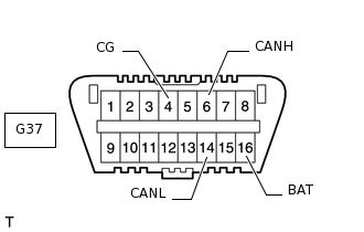
Measure the resistance according to the value(s) in the table below.
Terminal No. (Symbol)
Wiring Color
Switch Condition
Specified Condition
G37-6 (CANH) - G37-14 (CANL)
R - W
Engine switch off
54 to 69 Ω
G37-6 (CANH) - G37-4 (CG)
R - W-B
Engine switch off
200 Ω or higher
G37-14 (CANL) - G37-4 (CG)
W - W-B
Engine switch off
200 Ω or higher
G37-6 (CANH) - G37-16 (BAT)
R - GR
Engine switch off
6 kΩ or higher
G37-14 (CANL) - G37-16 (BAT)
W - GR
Engine switch off
6 kΩ or higher
CHECK ECM (for 1UR-FE)
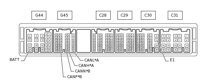
*A
for V1 Bus
*B
for Power Management Bus
Disconnect the C30, G44 and G45 ECM connectors.
Measure the resistance according to the value(s) in the table below.
Table 1. for V1 Bus Terminal No. (Symbol)
Wiring Color
Switch Condition
Specified Condition
G45-32 (CANH) - G45-31 (CANL)
R - W
Engine switch off
108 to 132 Ω
G45-32 (CANH) - C30-12 (E1)
R - BR
Engine switch off
200 Ω or higher
G45-31 (CANL) - C30-12 (E1)
W - BR
Engine switch off
200 Ω or higher
G45-32 (CANH) - G44-24 (BATT)
R - L
Engine switch off
6 kΩ or higher
G45-31 (CANL) - G44-24 (BATT)
W - L
Engine switch off
6 kΩ or higher
Table 2. for Power Management Bus Terminal No. (Symbol)
Wiring Color
Switch Condition
Specified Condition
G45-34 (CANP) - G45-33 (CANN)
BR - GR
Engine switch off
108 to 132 Ω
G45-34 (CANP) - C30-12 (E1)
BR - BR
Engine switch off
200 Ω or higher
G45-33 (CANN) - C30-12 (E1)
GR - BR
Engine switch off
200 Ω or higher
G45-34 (CANP) - G44-24 (BATT)
BR - L
Engine switch off
6 kΩ or higher
G45-33 (CANN) - G44-24 (BATT)
GR - L
Engine switch off
6 kΩ or higher
CHECK ECM (for 1GR-FE)
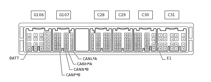
*A
for V1 Bus
*B
for Power Management Bus
Disconnect the C30, G106 and G107 ECM connectors.
Measure the resistance according to the value(s) in the table below.
Table 3. for V1 Bus Terminal No. (Symbol)
Wiring Color
Switch Condition
Specified Condition
G107-32 (CANH) - G107-31 (CANL)
R - W
Engine switch off
108 to 132 Ω
G107-32 (CANH) - C30-12 (E1)
R - BR
Engine switch off
200 Ω or higher
G107-31 (CANL) - C30-12 (E1)
W - BR
Engine switch off
200 Ω or higher
G107-32 (CANH) - G106-24 (BATT)
R - L
Engine switch off
6 kΩ or higher
G107-31 (CANL) - G106-24 (BATT)
W - L
Engine switch off
6 kΩ or higher
Table 4. for Power Management Bus Terminal No. (Symbol)
Wiring Color
Switch Condition
Specified Condition
G107-34 (CANP) - G107-33 (CANN)
BR - GR
Engine switch off
108 to 132 Ω
G107-34 (CANP) - C30-12 (E1)
BR - BR
Engine switch off
200 Ω or higher
G107-33 (CANN) - C30-12 (E1)
GR - BR
Engine switch off
200 Ω or higher
G107-34 (CANP) - G106-24 (BATT)
BR - L
Engine switch off
6 kΩ or higher
G107-33 (CANN) - G106-24 (BATT)
GR - L
Engine switch off
6 kΩ or higher
CHECK DRIVER SIDE JUNCTION BLOCK ASSEMBLY AND MAIN BODY ECU (MULTIPLEX NETWORK BODY ECU)
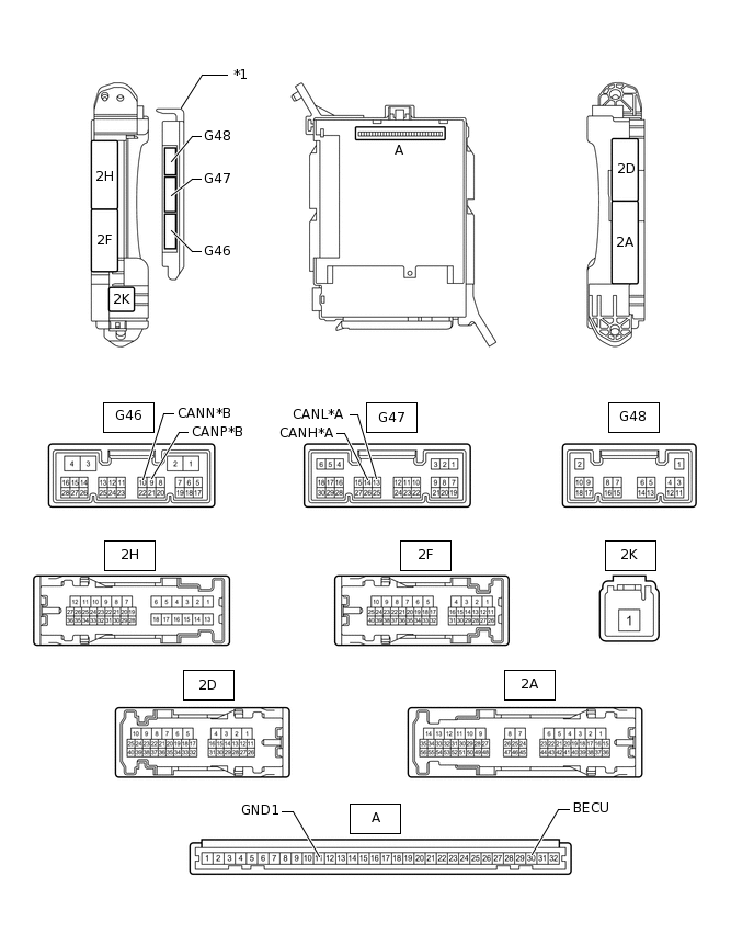
*A
for V1 Bus
B
for MS Bus
*1
Main Body ECU (Multiplex Network Body ECU)
-
-
Remove the main body ECU (multiplex network body ECU) (Click here).
Measure the resistance according to the value(s) in the table below.
Table 5. for V1 Bus Terminal No. (Symbol)
Wiring Color
Switch Condition
Specified Condition
G47-14 (CANH) - G47-13 (CANL)
L - W
Engine switch off
54 to 69 Ω
G47-14 (CANH) - A-11 (GND1)
L - None
Engine switch off
200 Ω or higher
G47-13 (CANL) - A-11 (GND1)
W - None
Engine switch off
200 Ω or higher
G47-14 (CANH) - A-30 (BECU)
L - None
Engine switch off
6 kΩ or higher
G47-13 (CANL) - A-30 (BECU)
W - None
Engine switch off
6 kΩ or higher
Table 6. for MS Bus Terminal No. (Symbol)
Wiring Color
Switch Condition
Specified Condition
G46-9 (CANP) - G46-10 (CANN)
P - W
Engine switch off
108 to 132 Ω
G46-9 (CANP) - A-11 (GND1)
P - None
Engine switch off
200 Ω or higher
G46-10 (CANN) - A-11 (GND1)
W - None
Engine switch off
200 Ω or higher
G46-9 (CANP) - A-30 (BECU)
P - None
Engine switch off
6 kΩ or higher
G46-10 (CANN) - A-30 (BECU)
W - None
Engine switch off
6 kΩ or higher
CHECK COMBINATION METER ASSEMBLY
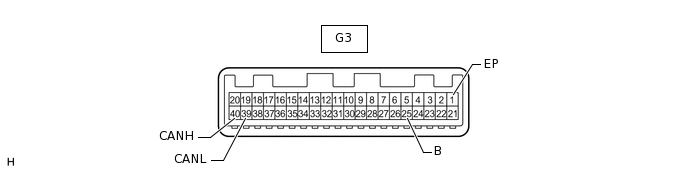
Disconnect the G3 combination meter assembly connector.
Measure the resistance according to the value(s) in the table below.
Terminal No. (Symbol)
Wiring Color
Switch Condition
Specified Condition
G3-40 (CANH) - G3-39 (CANL)
LG - W
Engine switch off
108 to 132 Ω
G3-40 (CANH) - G3-1 (EP)
LG - W-B
Engine switch off
200 Ω or higher
G3-39 (CANL) - G3-1 (EP)
W - W-B
Engine switch off
200 Ω or higher
G3-40 (CANH) - G3-25 (B)
LG - L
Engine switch off
6 kΩ or higher
G3-39 (CANL) - G3-25 (B)
W - L
Engine switch off
6 kΩ or higher
CHECK CENTER AIRBAG SENSOR ASSEMBLY
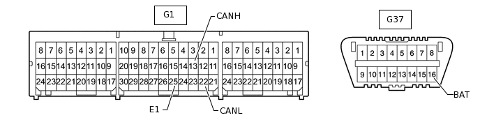
Disconnect the G1 center airbag sensor assembly connector.
Measure the resistance according to the value(s) in the table below.
Terminal No. (Symbol)
Wiring Color
Switch Condition
Specified Condition
G1-13 (CANH) - G1-22 (CANL)
Y - W
Engine switch off
54 to 69 Ω
G1-13 (CANH) - G1-25 (E1)
Y - W-B
Engine switch off
200 Ω or higher
G1-22 (CANL) - G1-25 (E1)
W - W-B
Engine switch off
200 Ω or higher
G1-13 (CANH) - G37-16 (BAT)
Y - GR
Engine switch off
6 kΩ or higher
G1-22 (CANL) - G37-16 (BAT)
W - GR
Engine switch off
6 kΩ or higher
CHECK MASTER CYLINDER SOLENOID (SKID CONTROL ECU)
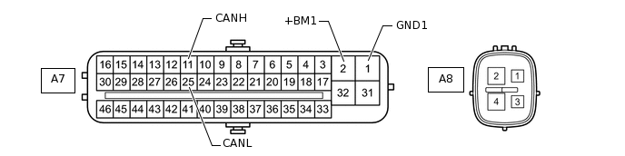
Disconnect the A7 master cylinder solenoid (skid control ECU) connector.
Measure the resistance according to the value(s) in the table below.
Terminal No. (Symbol)
Wiring Color
Switch Condition
Specified Condition
A7-11 (CANH) - A7-25 (CANL)
B - W
Engine switch off
54 to 69 Ω
A7-11 (CANH) - A7-1 (GND1)
B - W-B
Engine switch off
200 Ω or higher
A7-25 (CANL) - A7-1 (GND1)
W - W-B
Engine switch off
200 Ω or higher
A7-11 (CANH) - A7-2 (+BM1)
B - B
Engine switch off
6 kΩ or higher
A7-25 (CANL) - A7-2 (+BM1)
W - B
Engine switch off
6 kΩ or higher
CHECK SPIRAL WITH SENSOR CABLE SUB-ASSEMBLY (STEERING ANGLE SENSOR)
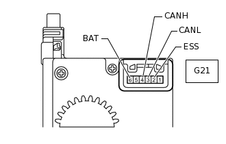
Disconnect the G21 spiral with sensor cable sub-assembly (steering angle sensor) connector.
Measure the resistance according to the value(s) in the table below.
Terminal No. (Symbol)
Wiring Color
Switch Condition
Specified Condition
G21-4 (CANH) - G21-3 (CANL)
G - W
Engine switch off
54 to 69 Ω
G21-4 (CANH) - G21-2 (ESS)
G - W-B
Engine switch off
200 Ω or higher
G21-3 (CANL) - G21-2 (ESS)
W - W-B
Engine switch off
200 Ω or higher
G21-4 (CANH) - G21-6 (BAT)
G - L
Engine switch off
6 kΩ or higher
G21-3 (CANL) - G21-6 (BAT)
W - L
Engine switch off
6 kΩ or higher
CHECK YAW RATE SENSOR ASSEMBLY
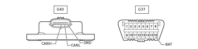
Disconnect the G40 yaw rate sensor assembly connector.
Measure the resistance according to the value(s) in the table below.
Terminal No. (Symbol)
Wiring Color
Switch Condition
Specified Condition
G40-3 (CANH) - G40-2 (CANL)
R - W
Engine switch off
54 to 69 Ω
G40-3 (CANH) - G40-1 (GND)
R - W-B
Engine switch off
200 Ω or higher
G40-2 (CANL) - G40-1 (GND)
W - W-B
Engine switch off
200 Ω or higher
G40-3 (CANH) - G37-16 (BAT)
R - GR
Engine switch off
6 kΩ or higher
G40-2 (CANL) - G37-16 (BAT)
W - GR
Engine switch off
6 kΩ or higher
CHECK CERTIFICATION ECU (SMART KEY ECU ASSEMBLY)
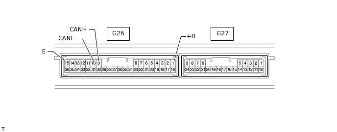
Disconnect the G26 certification ECU (smart key ECU assembly) connector.
Measure the resistance according to the value(s) in the table below.
Terminal No. (Symbol)
Wiring Color
Switch Condition
Specified Condition
G26-9 (CANH) - G26-10 (CANL)
P - W
Engine switch off
54 to 69 Ω
G26-9 (CANH) - G26-15 (E)
P - W-B
Engine switch off
200 Ω or higher
G26-10 (CANL) - G26-15 (E)
W - W-B
Engine switch off
200 Ω or higher
G26-9 (CANH) - G26-1 (+B)
P - V
Engine switch off
6 kΩ or higher
G26-10 (CANL) - G26-1 (+B)
W - V
Engine switch off
6 kΩ or higher
CHECK POWER MANAGEMENT CONTROL ECU
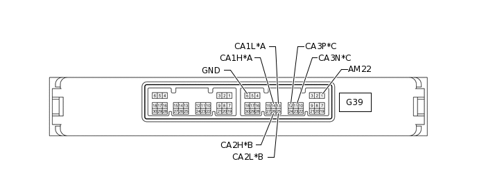
*A
for V1 Bus
*B
for V2 Bus
*C
for Power Management Bus
-
-
Disconnect the G39 power management control ECU connector.
Measure the resistance according to the value(s) in the table below.
Table 7. for V1 Bus Terminal No. (Symbol)
Wiring Color
Switch Condition
Specified Condition
G39-14 (CA1H) - G39-13 (CA1L)
BR - W
Engine switch off
54 to 69 Ω
G39-14 (CA1H) - G39-6 (GND)
BR - W-B
Engine switch off
200 Ω or higher
G39-13 (CA1L) - G39-6 (GND)
W - W-B
Engine switch off
200 Ω or higher
G39-14 (CA1H) - G39-1 (AM22)
BR - B
Engine switch off
6 kΩ or higher
G39-13 (CA1L) - G39-1 (AM22)
W - B
Engine switch off
6 kΩ or higher
Table 8. for V2 Bus Terminal No. (Symbol)
Wiring Color
Switch Condition
Specified Condition
G39-26 (CA2H) - G39-25 (CA2L)
V - W
Engine switch off
108 to 132 Ω
G39-26 (CA2H) - G39-6 (GND)
V - W-B
Engine switch off
200 Ω or higher
G39-25 (CA2L) - G39-6 (GND)
W - W-B
Engine switch off
200 Ω or higher
G39-26 (CA2H) - G39-1 (AM22)
V - B
Engine switch off
6 kΩ or higher
G39-25 (CA2L) - G39-1 (AM22)
W - B
Engine switch off
6 kΩ or higher
Table 9. for Power Management Bus Terminal No. (Symbol)
Wiring Color
Switch Condition
Specified Condition
G39-12 (CA3P) - G39-11 (CA3N)
BR - W
Engine switch off
108 to 132 Ω
G39-12 (CA3P) - G39-6 (GND)
BR - W-B
Engine switch off
200 Ω or higher
G39-11 (CA3N) - G39-6 (GND)
W - W-B
Engine switch off
200 Ω or higher
G39-12 (CA3P) - G39-1 (AM22)
BR - B
Engine switch off
6 kΩ or higher
G39-11 (CA3N) - G39-1 (AM22)
W - B
Engine switch off
6 kΩ or higher
CHECK MULTI-MEDIA MODULE RECEIVER ASSEMBLY (w/ Navigation System)
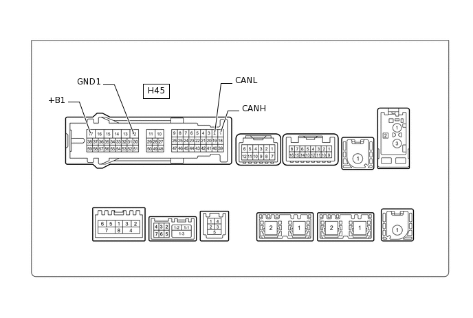
Disconnect the H45 multi-media module receiver assembly connector.
Measure the resistance according to the value(s) in the table below.
Terminal No. (Symbol)
Wiring Color
Switch Condition
Specified Condition
H45-1 (CANH) - H45-2 (CANL)
W - P
Engine switch off
54 to 69 Ω
H45-1 (CANH) - H45-12 (GND1)
W - BR
Engine switch off
200 Ω or higher
H45-2 (CANL) - H45-12 (GND1)
P - BR
Engine switch off
200 Ω or higher
H45-1 (CANH) - H45-17 (+B1)
W - SB
Engine switch off
6 kΩ or higher
H45-2 (CANL) - H45-17 (+B1)
P - SB
Engine switch off
6 kΩ or higher
CHECK MULTI-MEDIA MODULE RECEIVER ASSEMBLY (w/o Navigation System)
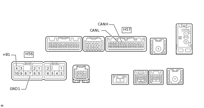
Disconnect the H56 and H57 multi-media module receiver assembly connectors.
Measure the resistance according to the value(s) in the table below.
Terminal No. (Symbol)
Wiring Color
Switch Condition
Specified Condition
H57-9 (CANH) - H57-10 (CANL)
W - P
Engine switch off
54 to 69 Ω
H57-9 (CANH) - H56-7 (GND1)
W - BR
Engine switch off
200 Ω or higher
H57-10 (CANL) - H56-7 (GND1)
P - BR
Engine switch off
200 Ω or higher
H57-9 (CANH) - H56-4 (+B1)
W - SB
Engine switch off
6 kΩ or higher
H57-10 (CANL) - H56-4 (+B1)
P - SB
Engine switch off
6 kΩ or higher
CHECK DCM (TELEMATICS TRANSCEIVER) (w/ Emergency Call Switch)
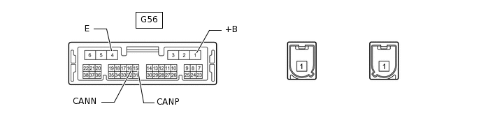
Disconnect the G56 DCM (telematics transceiver) connector.
Measure the resistance according to the value(s) in the table below.
Terminal No. (Symbol)
Wiring Color
Switch Condition
Specified Condition
G56-15 (CANP) - G56-16 (CANN)
V - W
Engine switch off
54 to 69 Ω
G56-15 (CANP) - G56-4 (E)
V - W-B
Engine switch off
200 Ω or higher
G56-16 (CANN) - G56-4 (E)
W - W-B
Engine switch off
200 Ω or higher
G56-15 (CANP) - G56-1 (+B)
V - SB
Engine switch off
6 kΩ or higher
G56-16 (CANN) - G56-1 (+B)
W - SB
Engine switch off
6 kΩ or higher
CHECK FOUR WHEEL DRIVE CONTROL ECU
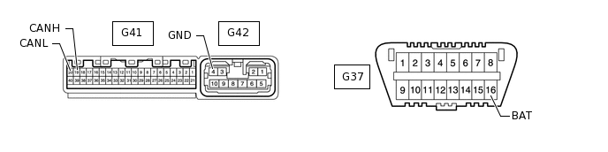
Disconnect the G41 and G42 four wheel drive control ECU connectors.
Measure the resistance according to the value(s) in the table below.
Terminal No. (Symbol)
Wiring Color
Switch Condition
Specified Condition
G41-19 (CANH) - G41-20 (CANL)
G - W
Engine switch off
54 to 69 Ω
G41-19 (CANH) - G42-4 (GND)
G - W-B
Engine switch off
200 Ω or higher
G41-20 (CANL) - G42-4 (GND)
W - W-B
Engine switch off
200 Ω or higher
G41-19 (CANH) - G37-16 (BAT)
G - GR
Engine switch off
6 kΩ or higher
G41-20 (CANL) - G37-16 (BAT)
W - GR
Engine switch off
6 kΩ or higher
CHECK SUSPENSION CONTROL ECU
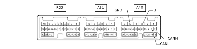
Disconnect the A40 suspension control ECU connector.
Measure the resistance according to the value(s) in the table below.
Terminal No. (Symbol)
Wiring Color
Switch Condition
Specified Condition
A40-7 (CANH) - A40-8 (CANL)
GR - W
Engine switch off
54 to 69 Ω
A40-7 (CANH) - A40-5 (GND)
GR - W-B
Engine switch off
200 Ω or higher
A40-8 (CANL) - A40-5 (GND)
W - W-B
Engine switch off
200 Ω or higher
A40-7 (CANH) - A40-3 (B)
GR - GR
Engine switch off
6 kΩ or higher
A40-8 (CANL) - A40-3 (B)
W - GR
Engine switch off
6 kΩ or higher
CHECK STABILIZER CONTROL ECU
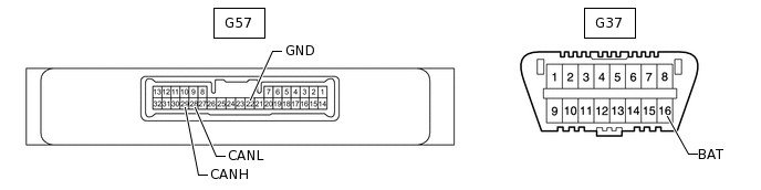
Disconnect the G57 stabilizer control ECU connector.
Measure the resistance according to the value(s) in the table below.
Terminal No. (Symbol)
Wiring Color
Switch Condition
Specified Condition
G57-29 (CANH) - G57-28 (CANL)
V - W
Engine switch off
54 to 69 Ω
G57-29 (CANH) - G57-22 (GND)
V - W-B
Engine switch off
200 Ω or higher
G57-28 (CANL) - G57-22 (GND)
W - W-B
Engine switch off
200 Ω or higher
G57-29 (CANH) - G37-16 (BAT)
V - GR
Engine switch off
6 kΩ or higher
G57-28 (CANL) - G37-16 (BAT)
W - GR
Engine switch off
6 kΩ or higher
CHECK SEAT BELT CONTROL ECU (w/ Pre-crash Safety System)
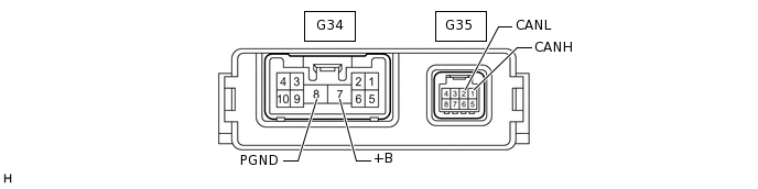
Disconnect the G34 and G35 seat belt control ECU connectors.
Measure the resistance according to the value(s) in the table below.
Terminal No. (Symbol)
Wiring Color
Switch Condition
Specified Condition
G35-1 (CANH) - G35-2 (CANL)
L - W
Engine switch off
54 to 69 Ω
G35-1 (CANH) - G34-8 (PGND)
L - W-B
Engine switch off
200 Ω or higher
G35-2 (CANL) - G34-8 (PGND)
W - W-B
Engine switch off
200 Ω or higher
G35-1 (CANH) - G34-7 (+B)
L - W
Engine switch off
6 kΩ or higher
G35-2 (CANL) - G34-7 (+B)
W - W
Engine switch off
6 kΩ or higher
CHECK DRIVING SUPPORT ECU ASSEMBLY (w/ Pre-crash Safety System)
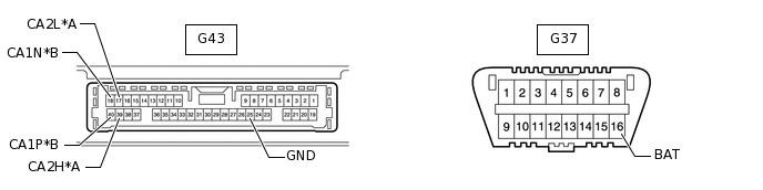
*A
for V2 Bus
*B
for Sensor Bus
Note:As disconnecting the connector to perform inspections may cause DTCs to be stored, clear DTCs after performing inspections.
As the connector may be damaged if a load of more than 10 kg (22 lb) is applied to it, do not apply any more load than necessary to the connector.
Disconnect the G43 driving support ECU assembly connector.
Measure the resistance according to the value(s) in the table below.
Table 10. for V2 Bus Terminal No. (Symbol)
Wiring Color
Switch Condition
Specified Condition
G43-39 (CA2H) - G43-17 (CA2L)
G - W
Engine switch off
54 to 69 Ω
G43-39 (CA2H) - G43-25 (GND)
G - BR
Engine switch off
200 Ω or higher
G43-17 (CA2L) - G43-25 (GND)
W - BR
Engine switch off
200 Ω or higher
G43-39 (CA2H) - G37-16 (BAT)
G - GR
Engine switch off
6 kΩ or higher
G43-17 (CA2L) - G37-16 (BAT)
W - GR
Engine switch off
6 kΩ or higher
Table 11. for Sensor Bus Terminal No. (Symbol)
Wiring Color
Switch Condition
Specified Condition
G43-40 (CA1P) - G43-18 (CA1N)
L - W
Engine switch off
108 to 132 Ω
G43-40 (CA1P) - G43-25 (GND)
L - BR
Engine switch off
200 Ω or higher
G43-18 (CA1N) - G43-25 (GND)
W - BR
Engine switch off
200 Ω or higher
G43-40 (CA1P) - G37-16 (BAT)
L - GR
Engine switch off
6 kΩ or higher
G43-18 (CA1N) - G37-16 (BAT)
W - GR
Engine switch off
6 kΩ or higher
CHECK PARKING ASSIST ECU (w/ Side Monitor System)
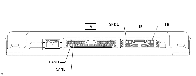
Disconnect the I5 and I6 parking assist ECU connectors.
Measure the resistance according to the value(s) in the table below.
Terminal No. (Symbol)
Wiring Color
Switch Condition
Specified Condition
I6-40 (CANH) - I6-39 (CANL)
B - W
Engine switch off
54 to 69 Ω
I6-40 (CANH) - I5-4 (GND1)
B - W-B
Engine switch off
200 Ω or higher
I6-39 (CANL) - I5-4 (GND1)
W - W-B
Engine switch off
200 Ω or higher
I6-40 (CANH) - I5-1 (+B)
B - L
Engine switch off
6 kΩ or higher
I6-39 (CANL) - I5-1 (+B)
W - L
Engine switch off
6 kΩ or higher
CHECK CLEARANCE WARNING ECU ASSEMBLY (w/ LEXUS Parking Assist-sensor System)
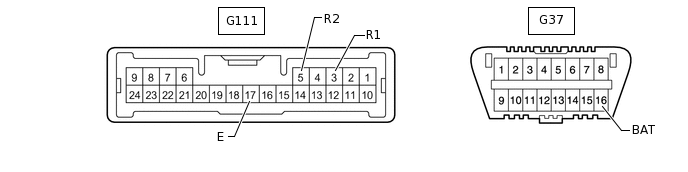
Disconnect the G111 clearance warning ECU assembly connector.
Measure the resistance according to the value(s) in the table below.
Terminal No. (Symbol)
Wiring Color
Switch Condition
Specified Condition
G111-3 (R1) - G111-5 (R2)
GR - W
Engine switch off
54 to 69 Ω
G111-3 (R1) - G111-17 (E)
GR - W-B
Engine switch off
200 Ω or higher
G111-5 (R2) - G111-17 (E)
W - W-B
Engine switch off
200 Ω or higher
G111-3 (R1) - G37-16 (BAT)
GR - GR
Engine switch off
6 kΩ or higher
G111-5 (R2) - G37-16 (BAT)
W - GR
Engine switch off
6 kΩ or higher
CHECK HEADLIGHT SWIVEL ECU ASSEMBLY
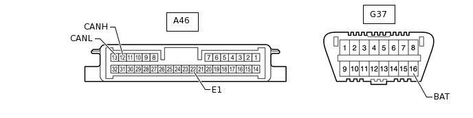
Disconnect the A46 headlight swivel ECU assembly connector.
Measure the resistance according to the value(s) in the table below.
Terminal No. (Symbol)
Wiring Color
Switch Condition
Specified Condition
A46-12 (CANH) - A46-13 (CANL)
V - W
Engine switch off
54 to 69 Ω
A46-12 (CANH) - A46-22 (E1)
V - W-B
Engine switch off
200 Ω or higher
A46-13 (CANL) - A46-22 (E1)
W - W-B
Engine switch off
200 Ω or higher
A46-12 (CANH) - G37-16 (BAT)
V - GR
Engine switch off
6 kΩ or higher
A46-13 (CANL) - G37-16 (BAT)
W - GR
Engine switch off
6 kΩ or higher
CHECK BLIND SPOT MONITOR SENSOR LH (w/ Blind Spot Monitor Sensor)
*A
for V2 Bus
*B
for Local Bus
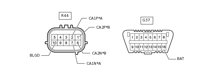
Disconnect the R44 blind spot monitor sensor LH connector.
Measure the resistance according to the value(s) in the table below.
Table 12. for V2 Bus Terminal No. (Symbol)
Wiring Color
Switch Condition
Specified Condition
R44-2 (CA1P) - R44-7 (CA1N)
G - W
Engine switch off
54 to 69 Ω
R44-2 (CA1P) - R44-10 (BLGD)
G - W-B
Engine switch off
200 Ω or higher
R44-7 (CA1N) - R44-10 (BLGD)
W - W-B
Engine switch off
200 Ω or higher
R44-2 (CA1P) - G37-16 (BAT)
G - GR
Engine switch off
6 kΩ or higher
R44-7 (CA1N) - G37-16 (BAT)
W - GR
Engine switch off
6 kΩ or higher
Table 13. for Local Bus Terminal No. (Symbol)
Wiring Color
Switch Condition
Specified Condition
R44-1 (CA2P) - R44-6 (CA2N)
P - W
Engine switch off
108 to 132 Ω
R44-1 (CA2P) - R44-10 (BLGD)
P - W-B
Engine switch off
200 Ω or higher
R44-6 (CA2N) - R44-10 (BLGD)
W - W-B
Engine switch off
200 Ω or higher
R44-1 (CA2P) - G37-16 (BAT)
P - GR
Engine switch off
6 kΩ or higher
R44-6 (CA2N) - G37-16 (BAT)
W - GR
Engine switch off
6 kΩ or higher
-
CHECK BLIND SPOT MONITOR SENSOR RH (w/ Blind Spot Monitor Sensor)
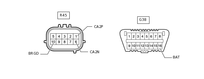
Disconnect the R45 blind spot monitor sensor RH connector.
Measure the resistance according to the value(s) in the table below.
Terminal No. (Symbol)
Wiring Color
Switch Condition
Specified Condition
R45-1 (CA2P) - R45-6 (CA2N)
P - W
Engine switch off
108 to 132 Ω
R45-1 (CA2P) - R45-10 (BRGD)
P - W-B
Engine switch off
200 Ω or higher
R45-6 (CA2N) - R45-10 (BRGD)
W - W-B
Engine switch off
200 Ω or higher
R45-1 (CA2P) - G37-16 (BAT)
P - GR
Engine switch off
6 kΩ or higher
R45-6 (CA2N) - G37-16 (BAT)
W - GR
Engine switch off
6 kΩ or higher
CHECK MULTIPLEX TILT AND TELESCOPIC ECU
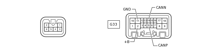
Disconnect the G33 multiplex tilt and telescopic ECU connector.
Measure the resistance according to the value(s) in the table below.
Terminal No. (Symbol)
Wiring Color
Switch Condition
Specified Condition
G33-5 (CANP) - G33-14 (CANN)
GR - W
Engine switch off
54 to 69 Ω
G33-5 (CANP) - G33-11 (GND)
GR - W-B
Engine switch off
200 Ω or higher
G33-14 (CANN) - G33-11 (GND)
W - W-B
Engine switch off
200 Ω or higher
G33-5 (CANP) - G33-2 (+B)
GR - G
Engine switch off
6 kΩ or higher
G33-14 (CANN) - G33-2 (+B)
W - G
Engine switch off
6 kΩ or higher
CHECK FRONT POWER SEAT SWITCH LH

Disconnect the b4 and b5 front power seat switch LH connectors.
Measure the resistance according to the value(s) in the table below.
Terminal No. (Symbol)
Wiring Color
Switch Condition
Specified Condition
b5-8 (CANP) - b5-7 (CANN)
L - W
Engine switch off
54 to 69 Ω
b5-8 (CANP) - b4-2 (GND)
L - W-B
Engine switch off
200 Ω or higher
b5-7 (CANN) - b4-2 (GND)
W - W-B
Engine switch off
200 Ω or higher
b5-8 (CANP) - b4-7 (+B1)
L - W
Engine switch off
6 kΩ or higher
b5-7 (CANN) - b4-7 (+B1)
W - W
Engine switch off
6 kΩ or higher
CHECK DRIVING SUPPORT SWITCH CONTROL ECU

Disconnect the G60 driving support switch control ECU connector.
Measure the resistance according to the value(s) in the table below.
Terminal No. (Symbol)
Wiring Color
Switch Condition
Specified Condition
G60-9 (CANP) - G60-10 (CANN)
R - W
Engine switch off
54 to 69 Ω
G60-9 (CANP) - G60-16 (GND)
R - W-B
Engine switch off
200 Ω or higher
G60-10 (CANN) - G60-16 (GND)
W - W-B
Engine switch off
200 Ω or higher
G60-9 (CANP) - G60-6 (+B)
R - L
Engine switch off
6 kΩ or higher
G60-10 (CANN) - G60-6 (+B)
W - L
Engine switch off
6 kΩ or higher
CHECK OUTER MIRROR CONTROL ECU ASSEMBLY RH
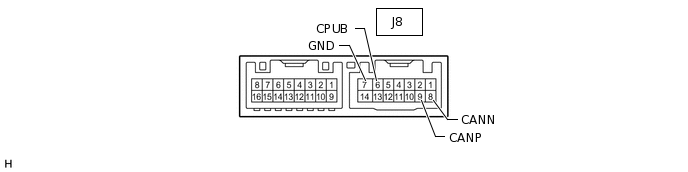
Disconnect the J8 outer mirror control ECU assembly RH connector.
Measure the resistance according to the value(s) in the table below.
Terminal No. (Symbol)
Wiring Color
Switch Condition
Specified Condition
J8-9 (CANP) - J8-8 (CANN)
G - W
Engine switch off
54 to 69 Ω
J8-9 (CANP) - J8-7 (GND)
G - W-B
Engine switch off
200 Ω or higher
J8-8 (CANN) - J8-7 (GND)
W - W-B
Engine switch off
200 Ω or higher
J8-9 (CANP) - J8-6 (CPUB)
G - L
Engine switch off
6 kΩ or higher
J8-8 (CANN) - J8-6 (CPUB)
W - L
Engine switch off
6 kΩ or higher
CHECK OUTER MIRROR CONTROL ECU ASSEMBLY LH
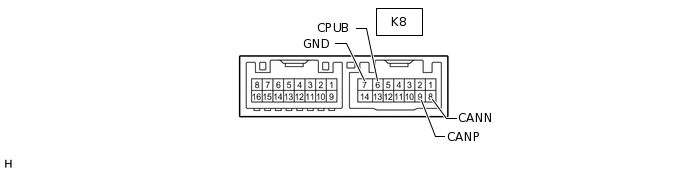
Disconnect the K8 outer mirror control ECU assembly LH connector.
Measure the resistance according to the value(s) in the table below.
Terminal No. (Symbol)
Wiring Color
Switch Condition
Specified Condition
K8-9 (CANP) - K8-8 (CANN)
B - W
Engine switch off
54 to 69 Ω
K8-9 (CANP) - K8-7 (GND)
B - W-B
Engine switch off
200 Ω or higher
K8-8 (CANN) - K8-7 (GND)
W - W-B
Engine switch off
200 Ω or higher
K8-9 (CANP) - K8-6 (CPUB)
B - L
Engine switch off
6 kΩ or higher
K8-8 (CANN) - K8-6 (CPUB)
W - L
Engine switch off
6 kΩ or higher
CHECK MILLIMETER WAVE RADAR SENSOR ASSEMBLY (w/ Pre-crash Safety System)
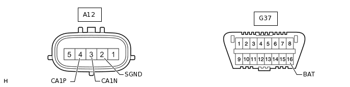
Disconnect the A12 millimeter wave radar sensor assembly connector.
Measure the resistance according to the value(s) in the table below.
Terminal No. (Symbol)
Wiring Color
Switch Condition
Specified Condition
A12-4 (CA1P) - A12-3 (CA1N)
LG - W
Engine switch off
108 to 132 Ω
A12-4 (CA1P) - A12-2 (SGND)
LG - BR
Engine switch off
200 Ω or higher
A12-3 (CA1N) - A12-2 (SGND)
W - BR
Engine switch off
200 Ω or higher
A12-4 (CA1P) - G37-16 (BAT)
LG - GR
Engine switch off
6 kΩ or higher
A12-3 (CA1N) - G37-16 (BAT)
W - GR
Engine switch off
6 kΩ or higher
CHECK AIR CONDITIONING AMPLIFIER ASSEMBLY
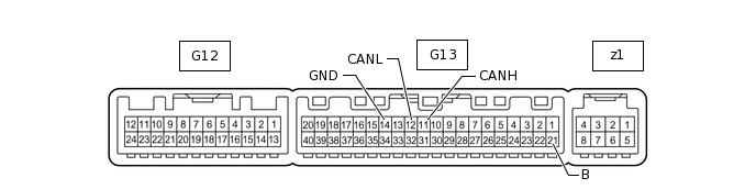
Disconnect the G13 air conditioning amplifier assembly connector.
Measure the resistance according to the value(s) in the table below.
Terminal No. (Symbol)
Wiring Color
Condition
Specified Condition
G13-11 (CANH) - G13-12 (CANL)
BR - Y
Engine switch off
54 to 69 Ω
G13-11 (CANH) - G13-14 (GND)
BR - W-B
Engine switch off
200 Ω or higher
G13-12 (CANL) - G13-14 (GND)
Y - W-B
Engine switch off
200 Ω or higher
G13-11 (CANH) - G13-21 (B)
BR - V
Engine switch off
6 kΩ or higher
G13-12 (CANL) - G13-21 (B)
Y - V
Engine switch off
6 kΩ or higher