SLIDE DOOR CLOSER SYSTEM Slide Door Closer Relay Power Source Circuit
DESCRIPTION
-
This circuit provides power to the slide door closer relay LH*1 or slide door closer relay RH*2.
-
*1: for LH Side
-
*2: for RH Side
w/o Power Slide Door
-
This circuit provides power to the door control relay assembly.
w/ Power Slide Door
WIRING DIAGRAM
-
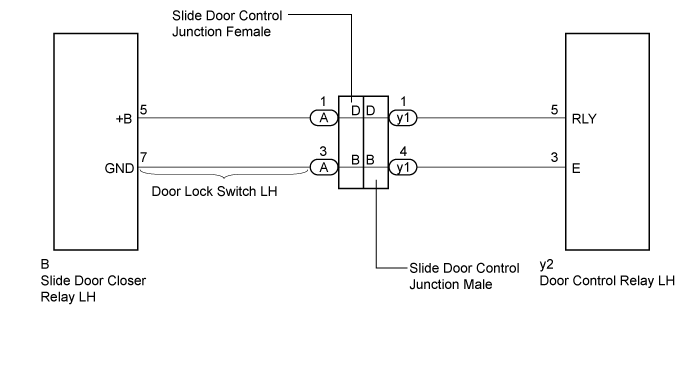
for LH Side (w/o Power Slide Door)
-
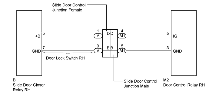
for RH Side (w/o Power Slide Door)
-
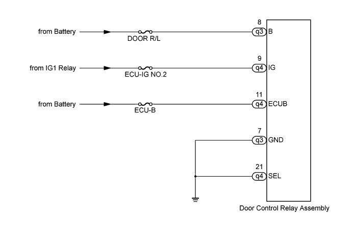
for LH Side (w/ Power Slide Door)
-
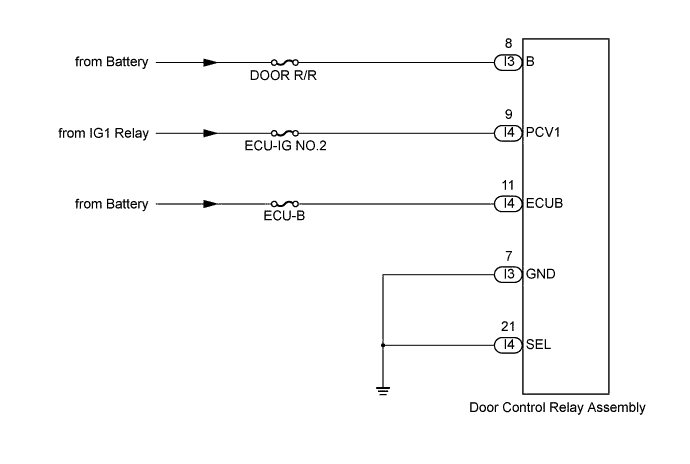
for RH Side (w/ Power Slide Door)
INSPECTION PROCEDURE
Note
Inspect the fuses for circuits related to this system before performing the following inspection procedure.
PROCEDURE
-
CHECK VEHICLE TYPE
-
Check vehicle type.
Result Result Proceed to w/ Power Slide Door A for LH Side (w/o Power Slide Door) B for RH Side (w/o Power Slide Door) C
B 
INSPECT SLIDE DOOR CONTROL JUNCTION FEMALE Click here
C
INSPECT SLIDE DOOR CONTROL JUNCTION FEMALE Click here
A 
-
-
CHECK HARNESS AND CONNECTOR (DOOR CONTROL RELAY ASSEMBLY - BATTERY AND BODY GROUND)
-
for LH Side
-
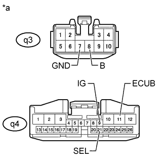
Text in Illustration *a Front view of wire harness connector
(to Door Control Relay Assembly)
Disconnect the door control relay assembly connectors.
-
Measure the resistance according to the value(s) in the table below.
Standard Resistance Tester Connection Condition Specified Condition q3-7(GND) - Body ground Always Below 1 Ω q4-21(SEL) - Body ground Always Below 1 Ω -
Measure the voltage according to the value(s) in the table below.
Standard Voltage Tester Connection Condition Specified Condition q3-8 (B) - Body ground Always 11 to 14 V q4-9 (IG) - Body ground Ignition switch ON 11 to 14 V q4-9 (IG) - Body ground Ignition switch off Below 1 V q4-11 (ECUB) - Body ground Always 11 to 14 V
-
-
for RH Side
-
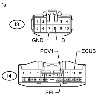
Text in Illustration *a Front view of wire harness connector
(to Door Control Relay Assembly)
Disconnect the door control relay assembly connectors.
-
Measure the resistance according to the value(s) in the table below.
Standard Resistance Tester Connection Condition Specified Condition I3-7(GND) - Body ground Always Below 1 Ω I4-21(SEL) - Body ground Always Below 1 Ω -
Measure the voltage according to the value(s) in the table below.
Standard Voltage Tester Connection Condition Specified Condition I3-8 (B) - Body ground Always 11 to 14 V I4-9 (PCV1) - Body ground Ignition switch ON 11 to 14 V I4-9 (PCV1) - Body ground Ignition switch off Below 1 V I4-11 (ECUB) - Body ground Always 11 to 14 V
-
NG 
REPAIR OR REPLACE HARNESS OR CONNECTOR
OK 
PROCEED TO NEXT SUSPECTED AREA SHOWN IN PROBLEM SYMPTOMS TABLE Click here
-
-
INSPECT SLIDE DOOR CONTROL JUNCTION FEMALE
-
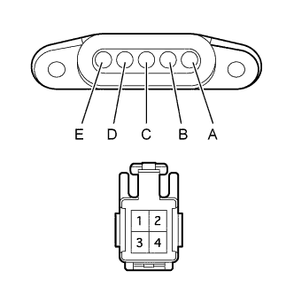
Remove the slide door control slide door control junction female Click here.
-
Measure the resistance according to the value(s) in the table below.
Standard Resistance Tester Connection Condition Specified Condition B - 3 Always Below 1 Ω D - 1 Always Below 1 Ω
NG
REPLACE SLIDE DOOR CONTROL JUNCTION FEMALE Click here
OK
-
-
INSPECT SLIDE DOOR CONTROL JUNCTION MALE
-
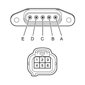
Remove the slide door control junction male.
-
Measure the resistance according to the value(s) in the table below.
Standard Resistance Tester Connection Condition Specified Condition B - 4 Always Below 1 Ω D - 1 Always Below 1 Ω
NG
REPLACE SLIDE DOOR CONTROL JUNCTION MALE
OK
-
-
INSPECT DOOR LOCK SWITCH LH
-
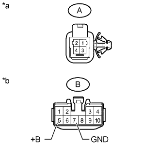
Text in Illustration *a Slide Door Control Junction Female Side *b Slide Door Closer Relay LH Side Disconnect the A and B door lock switch LH connectors.
-
Measure the resistance according to the value(s) in the table below.
Standard Resistance Tester Connection Condition Specified Condition A-1 - B-5 (+B) Always Below 1 Ω A-3 - B-7 (GND) Always Below 1 Ω
NG
REPLACE DOOR LOCK SWITCH LH
OK
-
-
CHECK HARNESS AND CONNECTOR (DOOR CONTROL RELAY LH - SLIDE DOOR CONTROL JUNCTION MALE)
-
Disconnect the y2 slide door closer relay LH connectors.
-
Disconnect the y1 slide door control junction male connector.
-
Measure the resistance according to the value(s) in the table below.
Standard Resistance Tester Connection Condition Specified Condition y2-5 (RLY) - y1-1 Always Below 1 Ω y2-3 (E) - y1-4 Always Below 1 Ω y2-5 (RLY) or y1-1 - Body ground Always 10 kΩ or higher y2-3 (E) or y1-4 - Body ground Always 10 kΩ or higher
NG
REPAIR OR REPLACE HARNESS OR CONNECTOR
OK
-
-
CHECK SLIDE DOOR CLOSER RELAY LH
-
Text in Illustration *a Front view of wire harness connector
(to Slide Door Closer Relay LH)
Disconnect the slide door closer relay LH connector.
-
Measure the resistance according to the value(s) in the table below.
Standard Resistance Tester Connection Condition Specified Condition B-7 (GND) - Body ground Always Below 1 Ω -
Measure the voltage according to the value(s) in the table below.
Standard Voltage Tester Connection Condition Specified Condition B-5 (+B) - Body ground Slide door OPEN → Halfway position Below 1 V → 11 to 14 V
NG
PROCEED TO NEXT SUSPECTED AREA SHOWN IN PROBLEM SYMPTOMS TABLE Click here
OK
REPLACE SLIDE DOOR CLOSER RELAY LH Click here
-
-
INSPECT SLIDE DOOR CONTROL JUNCTION FEMALE
-
Remove the slide door control slide door control junction female Click here.
-
Measure the resistance according to the value(s) in the table below.
Standard Resistance Tester Connection Condition Specified Condition B - 3 Always Below 1 Ω D - 1 Always Below 1 Ω
NG
REPLACE SLIDE DOOR CONTROL JUNCTION FEMALE Click here
OK
-
-
INSPECT SLIDE DOOR CONTROL JUNCTION MALE
-
Remove the slide door control junction male.
-
Measure the resistance according to the value(s) in the table below.
Standard Resistance Tester Connection Condition Specified Condition B - 5 Always Below 1 Ω D - 4 Always Below 1 Ω
NG
REPLACE SLIDE DOOR CONTROL JUNCTION MALE
OK
-
-
INSPECT DOOR LOCK SWITCH RH
-
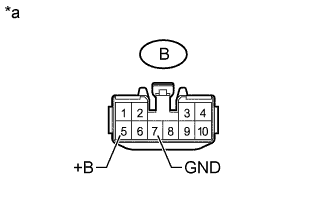
Text in Illustration *a Slide Door Control Junction Female Side *b Slide Door Closer Relay RH Side Disconnect the A and B door lock switch RH connectors.
-
Measure the resistance according to the value(s) in the table below.
Standard Resistance Tester Connection Condition Specified Condition A-3 - B-5 (+B) Always Below 1 Ω A-1 - B-7 (GND) Always Below 1 Ω
NG
REPLACE DOOR LOCK SWITCH RH
OK
-
-
CHECK HARNESS AND CONNECTOR (DOOR CONTROL RELAY RH - SLIDE DOOR CONTROL JUNCTION MALE)
-
Disconnect the M2 slide door closer relay RH connectors.
-
Disconnect the M1 slide door control junction male connector.
-
Measure the resistance according to the value(s) in the table below.
Standard Resistance Tester Connection Condition Specified Condition M2-5 (IG) - M1-4 Always Below 1 Ω M2-3 (GND) - M1-5 Always Below 1 Ω M2-5 (IG) or M1-4 - Body ground Always 10 kΩ or higher M2-3 (GND) - M1-5 - Body ground Always 10 kΩ or higher
NG
REPAIR OR REPLACE HARNESS OR CONNECTOR
OK
-
-
CHECK SLIDE DOOR CLOSER RELAY RH
-

Text in Illustration *a Front view of wire harness connector
(to Slide Door Closer Relay RH)
Disconnect the slide door closer relay RH connector.
-
Measure the resistance according to the value(s) in the table below.
Standard Resistance Tester Connection Condition Specified Condition B-7 (GND) - Body ground Always Below 1 Ω -
Measure the voltage according to the value(s) in the table below.
Standard Voltage Tester Connection Condition Specified Condition B-5 (+B) - Body ground Slide door OPEN → Halfway position Below 1 V → 11 to 14 V
NG
PROCEED TO NEXT SUSPECTED AREA SHOWN IN PROBLEM SYMPTOMS TABLE Click here
OK
REPLACE SLIDE DOOR CLOSER RELAY RH Click here
-