CONDENSER REMOVAL
PROCEDURE
-
RECOVER REFRIGERANT FROM REFRIGERATION SYSTEM (for HFC-134a(R134a))
-
RECOVER REFRIGERANT FROM REFRIGERATION SYSTEM (for HFO-1234yf(R1234yf))
-
REMOVE FRONT BUMPER ASSEMBLY
-
REMOVE INLET NO. 1 AIR CLEANER
-
REMOVE HOOD LOCK RELEASE LEVER PROTECTOR
-
REMOVE HOOD LOCK CONTROL CABLE COVER (for RHD)
-
DISCONNECT HOOD LOCK CONTROL CABLE ASSEMBLY
-
REMOVE HOOD LOCK ASSEMBLY
-
DISCONNECT ENGINE ROOM MAIN WIRE
-
REMOVE UPPER RADIATOR SUPPORT
-
DISCONNECT LIQUID TUBE SUB-ASSEMBLY A
-
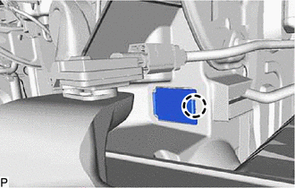
Disengage the claw to open the service hole cover.
-
Remove the bolt.
-
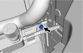
Remove the bolt and disconnect the liquid tube sub-assembly A from the cooler condenser assembly.
-
Remove the O-ring from the liquid tube sub-assembly A.
Note
Seal the openings of the disconnected parts using vinyl tape to prevent entry of moisture and foreign matter.
-
-
DISCONNECT NO. 1 COOLER REFRIGERANT DISCHARGE HOSE
-
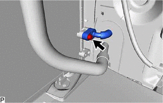
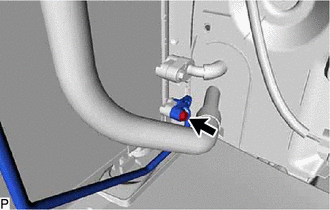
Remove the bolt and disconnect the No. 1 cooler refrigerant discharge hose from the cooler condenser assembly.
-
Remove the O-ring from the No. 1 cooler refrigerant discharge hose.
Note
Seal the openings of the disconnected parts using vinyl tape to prevent entry of moisture and foreign matter.
-
-
REMOVE COOLER CONDENSER ASSEMBLY
-
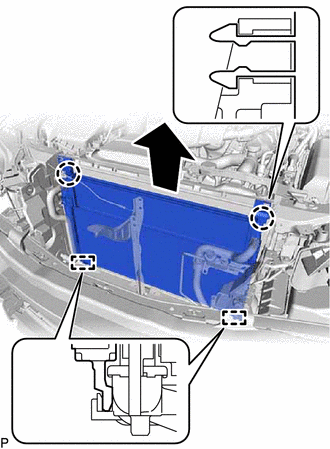
Disengage the 2 claws.
-
Disengage the 2 guides as shown in the illustration.
-
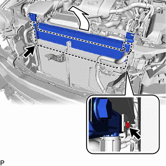
Remove the 2 bolts.
-
Pull the radiator assembly (for Inverter) as shown in the illustration.
-
Remove the cooler condenser assembly.
-