REAR SUSPENSION MEMBER REMOVAL
PROCEDURE
REMOVE REAR WHEELS
REMOVE UPPER CONSOLE PANEL SUB-ASSEMBLY
LOOSEN NO. 2 WIRE ADJUSTING NUT
REMOVE TAIL EXHAUST PIPE ASSEMBLY
REMOVE REAR SUSPENSION ARM COVER LH
REMOVE REAR SUSPENSION ARM COVER RH
Tip:Perform the same procedure as for the LH side.
REMOVE REAR FLOOR SIDE MEMBER COVER LH
-
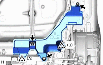
Remove the 2 bolts, nut and clip (A).
Disengage the clip (B) and remove the rear floor side member cover LH.
-
REMOVE REAR FLOOR SIDE MEMBER COVER RH
for 1ZR-FAE, 8NR-FTS:
-
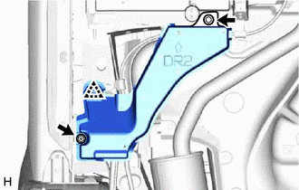
Remove the bolt and nut.
Disengage the clip and remove the rear floor side member cover RH.
-
for 1WW:
-
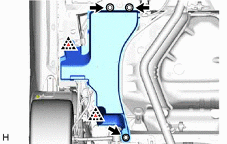
Remove the 3 bolts.
Disengage the 2 clips and remove the rear floor side member cover RH.
-
DISCONNECT SKID CONTROL SENSOR WIRE LH
DISCONNECT SKID CONTROL SENSOR WIRE RH
Tip:Perform the same procedure as for the LH side.
REMOVE REAR HEIGHT CONTROL SENSOR SUB-ASSEMBLY (w/ Height Control Sensor)
REMOVE PARKING BRAKE LEVER PROTECTOR (for LH Side)
REMOVE PARKING BRAKE LEVER PROTECTOR (for RH Side)
Tip:Perform the same procedure as for the LH side.
SEPARATE NO. 3 PARKING BRAKE CABLE ASSEMBLY
SEPARATE NO. 2 PARKING BRAKE CABLE ASSEMBLY
Tip:Perform the same procedure as for the No. 3 parking brake cable assembly.
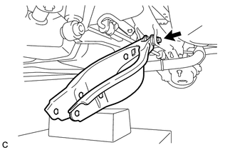
SEPARATE REAR DISC BRAKE CALIPER ASSEMBLY LH
SEPARATE REAR DISC BRAKE CALIPER ASSEMBLY RH
Tip:Perform the same procedure as for the LH side.
REMOVE REAR DISC
Remove the 2 rear discs.
REMOVE REAR NO. 1 SUSPENSION ARM ASSEMBLY LH
REMOVE REAR NO. 1 SUSPENSION ARM ASSEMBLY RH
Tip:Perform the same procedure as for the LH side.
REMOVE REAR AXLE ASSEMBLY (for LH Side)
-
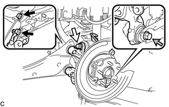

Bolt (A)

Bolt (B)

Bolt (C)
Loosen the 2 bolts (A), bolt (B) and bolt (C).
Note:Because the nuts have their own stoppers, do not turn the nuts. Loosen the bolts with the nuts secured.
Do not remove the bolts.
-
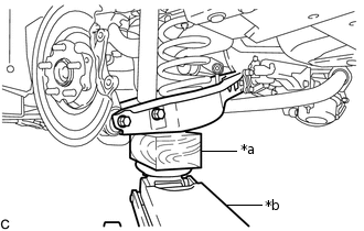
*a
Wooden Block
*b
Jack
Use a jack and wooden block to keep the rear No. 2 suspension arm assembly LH level.
CAUTION:Do not jack up the rear No. 2 suspension arm assembly LH too high as the vehicle may fall.
Note:When jacking up the rear No. 2 suspension arm assembly LH, be sure to jack it up slowly.
Make sure to perform this operation with the vehicle kept as low as possible.
-
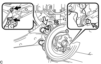
*1
No. 2 Flexible Hose Bracket
Bolt (A)
Bolt (B)
Bolt (C)
Remove the 2 bolts (A) and separate the rear trailing arm assembly from the rear axle assembly.
Remove the bolt (B), nut and No. 2 flexible hose bracket, and then separate the rear upper control arm assembly from the rear axle assembly.
Note:Because the nut has its own stopper, do not turn the nut. Loosen the bolt with the nut secured.
Remove the bolt (C), nut and rear axle assembly from the rear No. 2 suspension arm assembly LH.
Note:Because the nut has its own stopper, do not turn the nut. Loosen the bolt with the nut secured.
-
REMOVE REAR AXLE ASSEMBLY (for RH Side)
Tip:Perform the same procedure as for the LH side.
REMOVE REAR STABILIZER LINK ASSEMBLY LH
REMOVE REAR STABILIZER LINK ASSEMBLY RH
Tip:Perform the same procedure as for the LH side.
REMOVE REAR SUSPENSION MEMBER BRACE LH
REMOVE REAR SUSPENSION MEMBER BRACE RH
Tip:Perform the same procedure as for the LH side.
REMOVE REAR NO. 2 SUSPENSION ARM ASSEMBLY LH
-
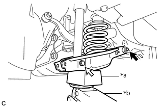
*a
Wooden Block
*b
Jack
Bolt (A)
Bolt (B)
Support the rear No. 2 suspension arm assembly LH using a jack and wooden block.
CAUTION:Do not jack up the rear No. 2 suspension arm assembly LH too high as the vehicle may fall.
Note:When jacking up the rear No. 2 suspension arm assembly LH, be sure to jack it up slowly.
Make sure to perform this operation with the vehicle kept as low as possible.
Loosen the bolt (A).
Note:Because the nut has its own stopper, do not turn the nut. Loosen the bolt with the nut secured.
Do not remove the bolt.
Remove the bolt (B) and nut, and then slowly lower the rear No. 2 suspension arm assembly LH, and remove the rear coil spring LH.
Note:Because the nut has its own stopper, do not turn the nut. Loosen the bolt with the nut secured.
-
Remove the bolt, nut and rear No. 2 suspension arm assembly LH from the rear suspension member sub-assembly.
Note:Because the nut has its own stopper, do not turn the nut. Loosen the bolt with the nut secured.
-
REMOVE REAR NO. 2 SUSPENSION ARM ASSEMBLY RH
Tip:Perform the same procedure as for the LH side.
REMOVE REAR UPPER COIL SPRING INSULATOR LH
REMOVE REAR UPPER COIL SPRING INSULATOR RH
Tip:Perform the same procedure as for the LH side.
REMOVE REAR LOWER COIL SPRING INSULATOR LH
REMOVE REAR LOWER COIL SPRING INSULATOR RH
Tip:Perform the same procedure as for the LH side.
REMOVE REAR STABILIZER BAR
REMOVE REAR SUSPENSION MEMBER SUB-ASSEMBLY
-
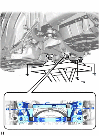
*a
Engine Lifter
*b
Attachment

Attachment placement location
Support the rear suspension member sub-assembly with an engine lifter using 4 attachments or equivalent tools as shown in the illustration.
Note:Make sure to secure the rear suspension member sub-assembly to prevent it from dropping.
Use the attachments to keep the rear suspension member sub-assembly level.
The rear suspension member sub-assembly is a heavy component. Make sure that it is supported securely.
Remove the 2 bolts, 2 rear suspension member rear lower stoppers, 2 nuts (A), 2 nuts (B) and rear suspension member lower stoppers LH and RH.
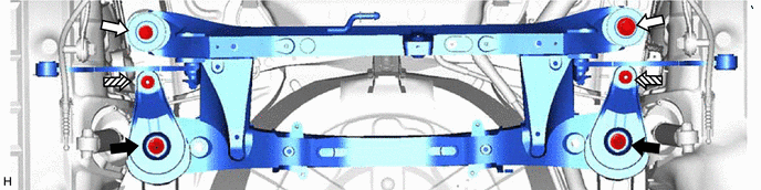
Nut (A)
Bolt
Nut (B)
-
-
Slowly lower the rear suspension member sub-assembly.
Note:When lowering the rear suspension member sub-assembly, be careful not to damage the vehicle body or other components installed on the vehicle.
-
REMOVE REAR SUSPENSION MEMBER UPPER STOPPER
-
Remove the 2 rear suspension member upper stoppers.
-
REMOVE REAR SUSPENSION MEMBER REAR UPPER STOPPER
-
Remove the 2 rear suspension member rear upper stoppers.
-
REMOVE REAR UPPER CONTROL ARM ASSEMBLY LH
-
Remove the bolt, nut and rear upper control arm assembly LH from the rear suspension member sub-assembly.
Note:Because the nut has its own stopper, do not turn the nut. Loosen the bolt with the nut secured.
-
REMOVE REAR UPPER CONTROL ARM ASSEMBLY RH
Tip:Perform the same procedure as for the LH side.
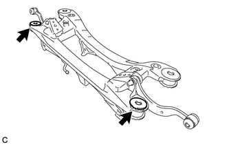
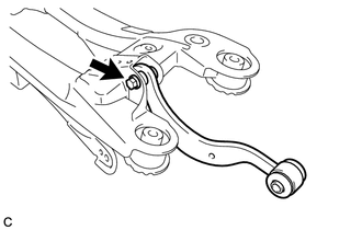
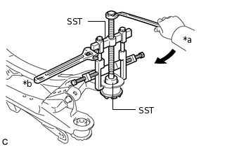
REMOVE REAR SUSPENSION MEMBER FRONT BODY MOUNTING CUSHION (for LH Side)
-
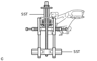
Install SST as shown in the illustration.
09830-10010
09830-01010
09830-01040
09830-01050
09950-40011
09951-04020
09952-04010
09954-04020
09955-04051
09958-04011
Note:Apply a small amount of grease to the threads and tip of SST (center bolt) before use.
-
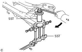
*a
Turn
*b
Hold
Using SST, separate the rear suspension member front body mounting cushion from the rear suspension member sub-assembly, while applying grease to the clearance between the rear suspension member front body mounting cushion and the rear suspension member sub-assembly.
09830-10010
09830-01010
09830-01040
09830-01050
09950-40011
09951-04020
09952-04010
09954-04020
09955-04051
09958-04011
Note:Set the claws of SST onto the rear suspension member sub-assembly securely.
Be careful as the rear suspension member front body mounting cushion may fly out.
The rear suspension member front body mounting cushion cannot be reused.
Remove SST and the rear suspension member front body mounting cushion from the rear suspension member sub-assembly.
-
REMOVE REAR SUSPENSION MEMBER FRONT BODY MOUNTING CUSHION (for RH Side)
Tip:Perform the same procedure as for the LH side.
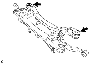
REMOVE REAR SUSPENSION MEMBER REAR BODY MOUNTING CUSHION LH
-
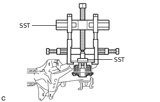
Install SST as shown in the illustration.
09950-40011
09951-04020
09952-04010
09953-04030
09954-04010
09955-04051
09957-04010
09958-04011
09950-60010
09951-00320
09952-06010
Note:Apply a small amount of grease to the threads and tip of SST (center bolt) before use.
-
*a
Turn
*b
Hold
Using SST, remove the rear suspension member rear body mounting cushion LH from the rear suspension member sub-assembly, while applying grease to the clearance between the rear suspension member rear body mounting cushion LH and the rear suspension member sub-assembly.
09950-40011
09951-04020
09952-04010
09953-04030
09954-04010
09955-04051
09957-04010
09958-04011
09950-60010
09951-00320
09952-06010
Note:Set the claws of SST onto the rear suspension member sub-assembly securely.
Be careful as the rear suspension member rear body mounting cushion LH may fly out.
The rear suspension member rear body mounting cushion LH cannot be reused.
-
REMOVE REAR SUSPENSION MEMBER REAR BODY MOUNTING CUSHION RH
Tip:Perform the same procedure as for the LH side.