KINETIC DYNAMIC SUSPENSION SYSTEM, Diagnostic DTC:C1882/82
| DTC Code | DTC Name |
|---|---|
| C1882/82 | Power Supply Voltage Malfunction |
DESCRIPTION
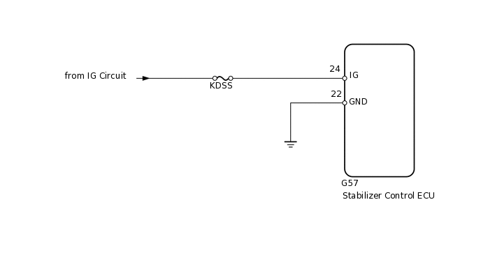
The stabilizer control ECU recognizes the engine switch on (IG) signal based on the voltage input to the IG terminal.
DTC No. |
Detection Item |
DTC Detection Condition |
Trouble Area |
|---|---|---|---|
C1882/82 |
Power Supply Voltage Malfunction |
The IG terminal voltage is 10 V or less or 16 V or higher for 0.5 seconds |
|
WIRING DIAGRAM
CAUTION / NOTICE / HINT
Inspect the fuses for circuits related to this system before performing the following inspection procedure.
PROCEDURE
READ VALUE USING INTELLIGENT TESTER (IG POWER SOURCE VOLTAGE)
Turn the engine switch off.
Connect the intelligent tester to the DLC3.
Turn the engine switch on (IG).
Turn the intelligent tester on.
Enter the following menus: Chassis / KDSS / Data List.
Select the item below in the Data List, and read the value displayed on the intelligent tester.
Chassis > KDSS > Data List
Tester Display
Measurement Item
Range
Normal Condition
Diagnostic Note
IG Power Source Voltage
IG Power Source Voltage
Min.: 0.0 V
Max.: 25.5 V
Engine switch on (IG): 11 to 14 V
-
Standard voltage
11 to 14 V
Result
Result
OK
NG
NG CHECK HARNESS AND CONNECTOR (IG TERMINAL)Click here
RECONFIRM DTC
Clear the DTCs.
Chassis > KDSS > Clear DTCs
Check for DTCs.
Result
Result
Proceed to
DTC is output
A
DTC is not output
B
Chassis > KDSS > Trouble Codes
CHECK HARNESS AND CONNECTOR (IG TERMINAL)
Disconnect the stabilizer control ECU connector.
-
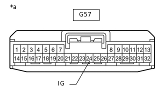
*a
Front view of wire harness connector
(to Stabilizer Control ECU)
Measure the voltage according to the value(s) in the table below.
Standard Voltage
Tester Connection
Switch Condition
Specified Condition
G57-24 (IG) - Body ground
Engine switch on (IG)
11 to 14 V
Result
Result
OK
NG
NG REPAIR OR REPLACE HARNESS OR CONNECTOR
CHECK HARNESS AND CONNECTOR (GND TERMINAL)
Disconnect the stabilizer control ECU connector.
Measure the resistance according to the value(s) in the table below.
Standard Resistance
Tester Connection
Condition
Specified Condition
G57-22 (GND) - Body ground
Always
Below 1 Ω
Result
Result
OK
NG
NG REPAIR OR REPLACE HARNESS OR CONNECTOR