PRE-COLLISION SYSTEM Heater Relay Circuit
| DTC Code | DTC Name |
|---|---|
| Heater Relay Circuit |
DESCRIPTION
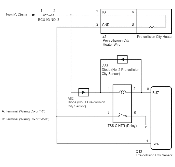
The pre-collision city sensor turns the pre-collision city heater on and off by operating the TSS C HTR relay (relay).
WIRING DIAGRAM
CAUTION / NOTICE / HINT
Inspect the fuses for circuits related to this system before performing the following procedure.
PROCEDURE
CHECK HARNESS AND CONNECTOR (PRE-COLLISION CITY HEATER POWER SOURCE CIRCUIT)
-
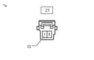
*a
Front view of wire harness connector
(to Pre-collision City Heater Wire)
Disconnect the Z1 pre-collision city heater wire connector.
Measure the voltage according to the value(s) in the table below.
Standard Voltage
Tester Connection
Condition
Specified Condition
Z1-1 (IG) - Body ground
Ignition switch ON
11 to 14 V
Ignition switch off
Below 1 V
Connect the Z1 pre-collision city heater wire connector.
Result
Proceed to
OK
NG
NG REPAIR OR REPLACE HARNESS OR CONNECTOR (PRE-COLLISION CITY HEATER POWER SOURCE CIRCUIT)
-
CHECK TERMINAL VOLTAGE (GND TERMINAL)
-
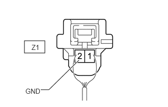
*a
Component with harness connected
(Pre-collision City Heater Wire)
Measure the voltage according to the value(s) in the table below.
Standard Voltage
Tester Connection
Condition
Specified Condition
Z1-2 (GND) - Body ground
Ignition switch ON
11 to 14 V
Ignition switch off
Below 1 V
Result
Proceed to
OK
NG
NG INSPECT PRE-COLLISION CITY HEATER WIREClick here
-
INSPECT TSS C HTR RELAY (RELAY)
Remove the TSS C HTR relay (relay).
Inspect the TSS C HTR relay (relay).
Install the TSS C HTR relay (relay).
Result
Proceed to
OK
NG
NG REPLACE TSS C HTR RELAY (RELAY)
CHECK HARNESS AND CONNECTOR (PRE-COLLISION CITY HEATER WIRE - TSS C HTR RELAY (RELAY) AND PRE-COLLISION CITY SENSOR)
Turn the ignition switch off.
Disconnect the Z1 pre-collision city heater wire connector.
Disconnect the Q12 pre-collision city sensor connector.
Remove the TSS C HTR relay (relay).
Measure the resistance according to the value(s) in the table below.
Standard Resistance
Tester Connection
Condition
Specified Condition
Z1-2 (GND) - TSS C HTR relay (relay) holder terminal 3
Always
Below 1 Ω
Z1-2 (GND) - Q12-1 (SPR)
Always
Below 1 Ω
Q12-1 (SPR) - TSS C HTR relay (relay) holder terminal 3
Always
Below 1 Ω
Z1-2 (GND), Q12-1 (SPR) or TSS C HTR relay (relay) holder terminal 3 - Body ground
Always
10 kΩ or higher
Connect the Z1 pre-collision city heater wire connector.
Connect the Q12 pre-collision city sensor connector.
Install the TSS C HTR relay (relay).
Result
Proceed to
OK
NG
NG REPAIR OR REPLACE HARNESS OR CONNECTOR (PRE-COLLISION CITY HEATER WIRE - TSS C HTR RELAY (RELAY) OR PRE-COLLISION CITY SENSOR)
CHECK HARNESS AND CONNECTOR (TSS C HTR RELAY (RELAY) - BODY GROUND)
Remove the TSS C HTR relay (relay).
Measure the resistance according to the value(s) in the table below.
Standard Resistance
Tester Connection
Condition
Specified Condition
TSS C HTR relay (relay) holder terminal 5 - Body ground
Always
Below 1 Ω
Install the TSS C HTR relay (relay).
Result
Proceed to
OK
NG
NG REPAIR OR REPLACE HARNESS OR CONNECTOR (TSS C HTR RELAY (RELAY) - BODY GROUND)
INSPECT PRE-COLLISION CITY HEATER WIRE
Disconnect the Z1 pre-collision city heater wire connector.
Disconnect terminal A and B.
-
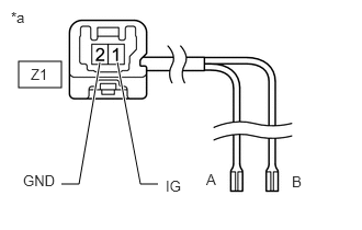
*a
Pre-collision City Heater Wire
A
Terminal (Wiring Color "R")
B
Terminal (Wiring Color "W-B")
Measure the resistance according to the value(s) in the table below.
Standard Resistance
Tester Connection
Condition
Specified Condition
Z1-1 (IG) - A
Always
Below 1 Ω
Z1-2 (GND) - B
Always
Below 1 Ω
Z1-1 (IG) or A - Body ground
Always
10 kΩ or higher
Z1-2 (GND) or B - Body ground
Always
10 kΩ or higher
Connect the Z1 pre-collision city heater wire connector.
Connect terminal A and B.
Result
Proceed to
OK
NG