REAR SEAT ENTERTAINMENT SYSTEM Television Display does not Turn ON
DESCRIPTION
-
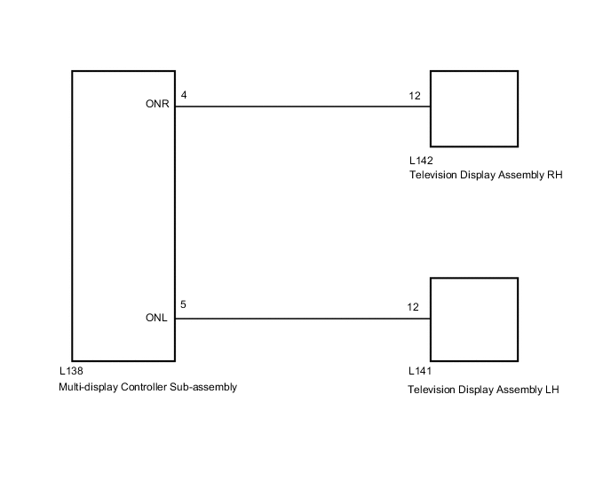
The multi-display controller sub-assembly and television display assembly are connected using this power on output signal lines.
-
Using this circuit, the multi-display controller sub-assembly sends power ON signal to the television display assembly.
WIRING DIAGRAM
CAUTION / NOTICE / HINT
Tech Tips
Depending on the parts that are replaced during vehicle inspection or maintenance, performing initialization, registration or calibration may be needed. Refer to Precaution for Rear Seat Entertainment System.
PROCEDURE
-
CHECK OPERATION
-
Check which television display assembly does not operate.
Result Result Proceed to Television display assembly LH does not operate. A Television display assembly RH does not operate. B Television display assembly LH and television display assembly RH does not operate. C
B 
CHECK MULTI-DISPLAY CONTROLLER SUB-ASSEMBLY Click here
C
CHECK HARNESS AND CONNECTOR (MULTI-DISPLAY CONTROLLER SUB-ASSEMBLY - TELEVISION DISPLAY ASSEMBLY) Click here
A 
-
-
CHECK MULTI-DISPLAY CONTROLLER SUB-ASSEMBLY
-
Disconnect the L142 television display assembly RH connector.
-
Measure the voltage according to the value(s) in the table below.
Standard Voltage Tester Connection Condition Specified Condition L142-12 - Body ground Engine switch on (ACC) 11 to 14 V Result Proceed to OK NG
NG 
REPLACE MULTI-DISPLAY CONTROLLER SUB-ASSEMBLY Click here
OK
-
-
CHECK HARNESS AND CONNECTOR (MULTI-DISPLAY CONTROLLER SUB-ASSEMBLY - TELEVISION DISPLAY ASSEMBLY RH)
-
Disconnect the L138 multi-display controller sub-assembly connector.
-
Disconnect the L142 television display assembly RH connector.
-
Measure the resistance according to the value(s) in the table below.
Standard Resistance Tester Connection Condition Specified Condition L138-4 (ONR) - L142-12 Always Below 1 Ω L138-4 (ONR) - Body ground Always 10 kΩ or higher Result Proceed to OK NG
OK
PROCEED TO NEXT SUSPECTED AREA SHOWN IN PROBLEM SYMPTOMS TABLE Click here
NG
REPAIR OR REPLACE HARNESS OR CONNECTOR
-
-
CHECK MULTI-DISPLAY CONTROLLER SUB-ASSEMBLY
-
Disconnect the L141 television display assembly LH connector.
-
Measure the voltage according to the value(s) in the table below.
Standard Voltage Tester Connection Condition Specified Condition L141-12 - Body ground Engine switch on (ACC) 11 to 14 V Result Proceed to OK NG
NG
REPLACE MULTI-DISPLAY CONTROLLER SUB-ASSEMBLY Click here
OK
-
-
CHECK HARNESS AND CONNECTOR (MULTI-DISPLAY CONTROLLER SUB-ASSEMBLY - TELEVISION DISPLAY ASSEMBLY RH)
-
Disconnect the L138 multi-display controller sub-assembly connector.
-
Disconnect the L141 television display assembly LH connector.
-
Measure the resistance according to the value(s) in the table below.
Standard Resistance Tester Connection Condition Specified Condition L138-5 (ONL) - L141-12 Always Below 1 Ω L138-5 (ONL) - Body ground Always 10 kΩ or higher Result Proceed to OK NG
OK
PROCEED TO NEXT SUSPECTED AREA SHOWN IN PROBLEM SYMPTOMS TABLE Click here
NG
REPAIR OR REPLACE HARNESS OR CONNECTOR
-
-
CHECK HARNESS AND CONNECTOR (MULTI-DISPLAY CONTROLLER SUB-ASSEMBLY - TELEVISION DISPLAY ASSEMBLY)
-
Disconnect the L138 multi-display controller sub-assembly connector.
-
Disconnect the L142 television display assembly RH connector.
-
Disconnect the L141 television display assembly LH connector.
-
Measure the resistance according to the value(s) in the table below.
Standard Resistance Tester Connection Condition Specified Condition L138-4 (ONR) - L142-12 Always Below 1 Ω L138-5 (ONL) - L141-12 Always Below 1 Ω L138-4 (ONR) - Body ground Always 10 kΩ or higher L138-5 (ONL) - Body ground Always 10 kΩ or higher Result Proceed to OK NG
OK
REPLACE MULTI-DISPLAY CONTROLLER SUB-ASSEMBLY Click here
NG
REPAIR OR REPLACE HARNESS OR CONNECTOR
-