TOYOTA PARKING ASSIST-SENSOR SYSTEM
-
FUNCTION OF MAIN COMPONENTS
-
The components have the following functions:
Component Function No. 1 Ultrasonic Sensor Detects the distance between the vehicle and an obstacle. No. 1 Clearance Warning Buzzer Sounds to inform the driver according to the distance to the obstacle. Clearance Warning ECU Assembly
-
Judges the approximate distance between the vehicle and an obstacle based on signals from the No. 1 ultrasonic sensors. Output signals are sent to the telltale light assembly*1, radio and display receiver assembly*2*3, navigation receiver assembly*2*4 and combination meter assembly*2.
-
Sounds the No. 1 clearance warning buzzer.
Telltale Light Assembly*1
-
Clearance Warning Indicator Light
-
Clearance Sonar Switch
-
The indicator shows the location of the obstacle.
-
Operating this switch allows the operation of the Toyota parking assist-sensor system to be enabled or disabled.
Combination Meter Assembly Transmits received vehicle speed signals to the clearance warning ECU assembly. Multi-information display*2
-
Clearance Sonar Main Switch
-
Displays the location of the obstacle and the approximate distance between the vehicle and the obstacle.
-
Displays an indication of a malfunction or freezing of an ultrasonic sensor to inform the driver.
-
Operating this switch allows the operation of the Toyota parking assist-sensor system to be enabled or disabled.
Radio and Display Receiver Assembly*2*3 or Navigation Receiver Assembly*2*4
-
Displays the location of an obstacle and the approximate distance between the vehicle and the obstacle.
-
Displays an indication of a malfunction or freezing of an ultrasonic sensor to inform the driver.
-
The sound volume, distance required to sound the buzzer and distance required to trigger the display can be chosen on the setup screen for the Toyota parking assist-sensor system.
Park/Neutral Position Switch Assembly*5 Transmits the shift position signal to the ECM and TCM*7. Back-up Light Switch Assembly*6 Transmits the on/off signal of the back-up light switch assembly to ECM. ECM and TCM*7 Transmits the shift position signal to the clearance warning ECU assembly. Central Gateway ECU*2 Transmits the signal between the CAN communication bus. Air Conditioning Amplifier Assembly*2 Transmits the outside air temperature to the clearance warning ECU assembly. Main Body ECU (Multiplex Network Body ECU)*2*6 Outputs signals such as the parking brake signal to the clearance warning ECU assembly. *1: Models with 4-sensor type Toyota parking assist-sensor system
*2: Models with 8-sensor Toyota parking assist-sensor system
*3: Models with display audio system
*4: Models with navigation system
*5: Models with automatic transaxle or CVT
*6: Models with manual transaxle
*7: Models with U660F automatic transexle
-
-
-
OPERATING CONDITION
-
The operating condition of each sensor differs according to its installed position as shown in the table below:
Installation Position Operating Condition Front Corner*
-
Ignition switch is ON.
-
System is activated.
-
Shift lever is not in P.
-
Vehicle speed is approximately 10 km/h (6 mph) or less.
Front Center*
-
Ignition switch is ON.
-
System is activated.
-
Shift lever is not in P and R.
-
Vehicle speed is approximately 10 km/h (6 mph) or less.
Rear Corner
-
Ignition switch is ON.
-
System is activated.
-
Shift lever is in R.
Rear Center
-
Ignition switch is ON.
-
System is activated.
-
Shift lever is in R.
*: Models with 8-sensor type Toyota parking assist-sensor system
-
-
-
SYSTEM CONTROL
-
No. 1 Clearance Warning Buzzer
-
The on and off times of the No. 1 clearance warning buzzer vary as shown in the table below, depending on the distance between the obstacle and the ultrasonic sensor:
Detection Area Detection Distance (mm (in.)) Buzzer Sound Pattern On (msec.) Off (msec.) Front Corner* Long 500+/-50 to 400+/-40
(19.7+/-2.0 to 15.7+/-1.6)
200+/-20 200+/-20 Middle 400+/-40 to 300+/-30
(15.7+/-1.6 to 11.8+/-1.2)
100+/-10 100+/-10 Short 300+/-30 or less
(11.8+/-1.2 or less)
Continuous Sound 0 Front Center* Longest 1000+/-100 to 500+/-50
(39.4+/-3.9 to 19.7+/-2.0)
500+/-50 200+/-20 Long 500+/-50 to 400+/-40
(19.7+/-2.0 to 15.7+/-1.6)
200+/-20 200+/-20 Middle 400+/-40 to 300+/-30
(15.7+/-1.6 to 11.8+/-1.2)
100+/-10 100+/-10 Short 300+/-30 or less
(11.8+/-1.2 or less)
Continuous Sound 0 Rear Corner Long 550+/-60 to 400+/-40
(21.6+/-2.4 to 15.7+/-1.6)
200+/-20 200+/-20 Middle 400+/-40 to 300+/-30
(15.7+/-1.6 to 11.8+/-1.2)
100+/-10 100+/-10 Short 300+/-30 or less
(11.8+/-1.2 or less)
Continuous Sound 0 Rear Center Longest 1500+/-150 to 600+/-60
(59.1+/-5.9 to 23.6+/-2.4)
500+/-50 200+/-20 Long 600+/-60 to 450+/-50
(23.6+/-2.4 to 17.7+/-2.0)
200+/-20 200+/-20 Middle 450+/-50 to 350+/-40
(17.7+/-2.0 to 13.8+/-1.6)
100+/-10 100+/-10 Short 350+/-40 or less
(13.8+/-1.6 or less)
Continuous Sound 0 *: Models with 8-sensor type Toyota parking assist-sensor system
-
-
Detection Area
-
The detection areas of the No. 1 ultrasonic sensors are as shown in the following illustration.
-
These detection areas are applicable when positioning a 60 mm (2.36 in.) diameter pole parallel or perpendicular to the ground. The ranges vary depending on the measuring method and type of obstacle.
Figure 1. Corner Area
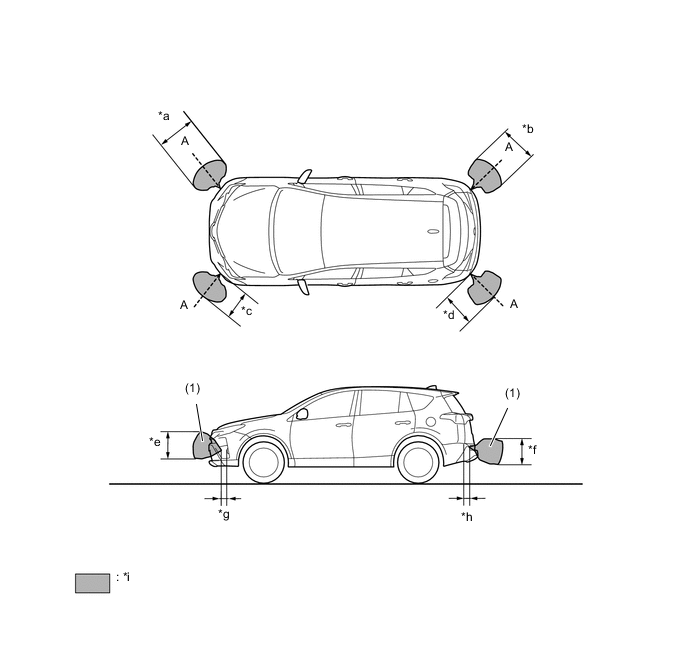
*a Approximately 660 mm (26.0 in.) *b Approximately 615 mm (24.2 in.) *c Approximately 500 mm (19.7 in.) *d Approximately 550 mm (21.7 in.) *e Approximately 375 mm (14.8 in.) *f Approximately 335 mm (13.2 in.) *g Approximately 100 mm (3.9 in.) *h Approximately 100 mm (3.9 in.) *i Detection Area - - Note
The ultrasonic sensor side view detection range area (labeled (1)) represents the cross section of the top view of the lines of detection range A. The area (1) does not represent the entire side view detection range.
Figure 2. Center Area
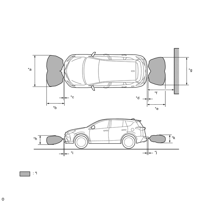
*a Approximately 1730 mm (68.1 in.) *b Approximately 1000 mm (39.4 in.) *c Approximately 30 mm (1.2 in.) *d Approximately 50 mm (2.0 in.) *e Approximately 1000 mm (39.4 in.) *f Approximately 1500 mm (59.1 in.) *g Approximately 1540 mm (60.6 in.) *h Approximately 435 mm (17.1 in.) *i Approximately 100 mm (3.9 in.) *j Approximately 100 mm (3.9 in.) *k Approximately 400 mm (15.7 in.) *l Detection Area
-
-
Clearance Warning Indicator Light (Models with 4-sensor Type Toyota Parking Assist-sensor System)
-
The driver is informed that there is an obstacle nearby by the flashing of the clearance warning indicator assembly located on the instrument panel. Also, the No. 1 clearance warning buzzer sounds simultaneously.
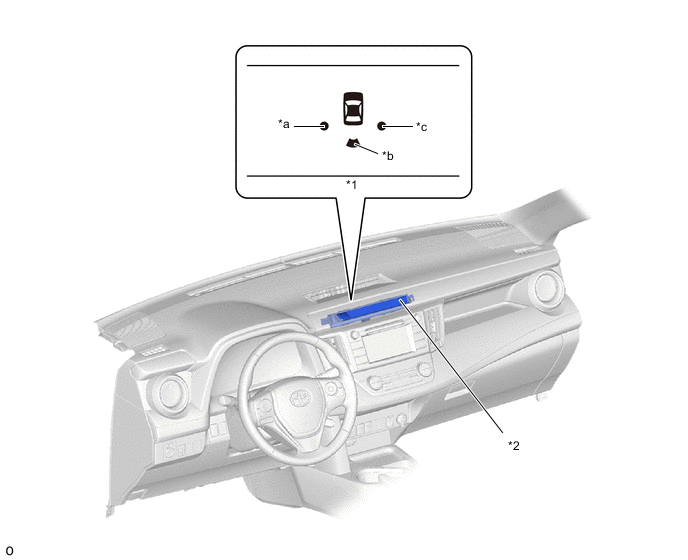
*1 Clearance Warning Indicator Light *2 Telltale Light Assembly *a Rear Corner LH *b Rear Center *c Rear Corner RH - -
-
-