CRUISE CONTROL SYSTEM(for 1ND-TV) Clutch Switch Circuit
| DTC Code | DTC Name |
|---|---|
| Clutch Switch Circuit |
DESCRIPTION
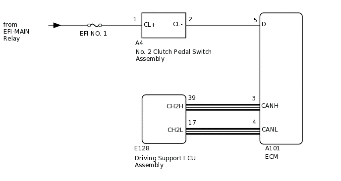
The ECM sends a signal such as a clutch switch signal to the driving support ECU assembly when the No. 2 clutch pedal switch assembly is depressed. The driving support ECU assembly cancels cruise control when the ECM receives the clutch switch signal.
WIRING DIAGRAM
CAUTION / NOTICE / HINT
Inspect the fuses for circuits related to this system before performing the following procedure.
PROCEDURE
READ VALUE USING GTS (CAN BUS CHECK)
Connect the GTS to the DLC3.
Turn the ignition switch to ON.
Enter the following menus: System Select / CAN Bus Check.
CAN Bus Check
Turn the ignition switch off.
Result
Result
Proceed to
All of the ECUs and sensors that are currently connected to the CAN communication system are displayed.
A
None of the ECUs and sensors that are currently connected to the CAN communication system are displayed, or some of them are not displayed.
B
CHECK DTC OUTPUT (HEALTH CHECK)
Connect the GTS to the DLC3.
Turn the ignition switch to ON.
Enter the following menus: System Select / Health Check.
Check for DTCs.
Turn the ignition switch off.
Result
Proceed to
No DTCs are output.
DTCs are output.
DTCs are output. GO TO DTC CHART
INSPECT NO. 2 CLUTCH PEDAL SWITCH ASSEMBLY
Inspect the No. 2 clutch pedal switch assembly.
Result
Proceed to
OK
NG
CHECK HARNESS AND CONNECTOR (NO. 2 CLUTCH PEDAL SWITCH ASSEMBLY - BATTERY)
Disconnect the A4 No. 2 clutch pedal switch assembly connector.
Measure the voltage according to the value(s) in the table below.
Standard Voltage
Tester Connection
Condition
Specified Condition
A4-1 (CL+) - Body ground
Ignition switch ON
11 to 14 V
A4-1 (CL+) - Body ground
Ignition switch off
Below 1 V
Reconnect the A4 No. 2 clutch pedal switch assembly connector.
Result
Proceed to
OK
NG
NG REPAIR OR REPLACE HARNESS OR CONNECTOR
CHECK HARNESS AND CONNECTOR (ECM - NO. 2 CLUTCH PEDAL SWITCH ASSEMBLY)
Disconnect the A4 No. 2 clutch pedal switch assembly connector.
Disconnect the A101 ECM connector.
Measure the resistance according to the value(s) in the table below.
Standard Resistance (Check for Open)
Tester Connection
Condition
Specified Condition
A101-5 (D) - A4-2 (CL-)
Always
Below 1 Ω
Standard Resistance (Check for Short)
Tester Connection
Condition
Specified Condition
A101-5 (D) or A4-2 (CL-) - Body ground
Always
10 kΩ or higher
Reconnect the A4 No. 2 clutch pedal switch assembly connector.
Reconnect the A101 ECM connector.
Result
Proceed to
OK
NG
NG REPAIR OR REPLACE HARNESS OR CONNECTOR (ECM - NO. 2 CLUTCH PEDAL SWITCH ASSEMBLY)