CONDENSER INSTALLATION
PROCEDURE
-
INSTALL COOLER CONDENSER ASSEMBLY
-
Temporarily install the cooler condenser assembly.
-
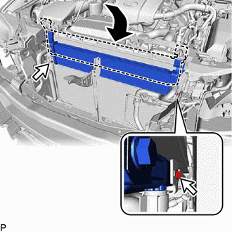
Temporarily install the radiator assembly (for Inverter) as shown in the illustration.
-
Install the radiator assembly (for Inverter) with the 2 bolts.
- Torque:
- 9.0 N*m { 92 kgf*cm, 80 in.*lbf }
-
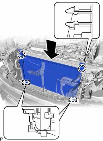
Engage the 2 guides as shown in the illustration.
-
Engage the 2 claws to install the cooler condenser assembly with radiator assembly (for Inverter).
-
-
CONNECT NO. 1 COOLER REFRIGERANT DISCHARGE HOSE
-
Remove the vinyl tape from the No. 1 cooler refrigerant discharge hose and the connecting part of the cooler condenser assembly.
-
Sufficiently apply compressor oil to a new O-ring and the fitting surface of the hose joint.
Compressor Oil ND-OIL 11 or equivalent -
Install the O-ring to the No. 1 cooler refrigerant discharge hose.
-
Connect the No. 1 cooler refrigerant discharge hose to the cooler condenser assembly with the bolt.
- Torque:
- 5.4 N*m { 55 kgf*cm, 48 in.*lbf }
-
-
CONNECT LIQUID TUBE SUB-ASSEMBLY A
-
Remove the vinyl tape from the liquid tube sub-assembly A and the connecting part of the cooler condenser assembly.
-
Sufficiently apply compressor oil to a new O-ring and the fitting surface of the tube joint.
Compressor Oil ND-OIL 11 or equivalent -
Install the O-ring to the liquid tube sub-assembly A.
-
Connect the liquid tube sub-assembly A to the cooler condenser assembly with the 2 bolts.
- Torque:
- 5.4 N*m { 55 kgf*cm, 48 in.*lbf }
-
Engage the claw to close the service hole cover.
-
-
INSTALL UPPER RADIATOR SUPPORT
-
CONNECT ENGINE ROOM MAIN WIRE
-
INSTALL HOOD LOCK ASSEMBLY
-
CONNECT HOOD LOCK CONTROL CABLE ASSEMBLY
-
INSTALL HOOD LOCK CONTROL CABLE COVER (for RHD)
-
INSTALL HOOD LOCK RELEASE LEVER PROTECTOR
-
INSTALL INLET NO. 1 AIR CLEANER
-
INSTALL MILLIMETER WAVE RADAR SENSOR ASSEMBLY (w/ Dynamic Radar Cruise Control System)
-
INSTALL FRONT BUMPER ASSEMBLY
-
CHARGE AIR CONDITIONING SYSTEM WITH REFRIGERANT (for HFC-134a(R134a))
-
CHARGE AIR CONDITIONING SYSTEM WITH REFRIGERANT (for HFO-1234yf(R1234yf))
-
WARM UP COMPRESSOR (for HFC-134a(R134a))
-
WARM UP COMPRESSOR (for HFO-1234yf(R1234yf))
-
INSPECT FOR REFRIGERANT LEAK (for HFC-134a(R134a))
-
INSPECT FOR REFRIGERANT LEAK (for HFO-1234yf(R1234yf))
-
ADJUST HOOD SUB-ASSEMBLY