CAN COMMUNICATION SYSTEM(w/o Central Gateway ECU) TERMINALS OF ECU
Note
-
After turning the power switch off, waiting time may be required before disconnecting the cable from the negative (-) auxiliary battery terminal. Therefore, make sure to read the disconnecting the cable from the negative (-) auxiliary battery terminal notices before proceeding with work Click here.
-
Turn the power switch off before measuring the resistances between CAN main bus lines and between CAN branch lines.
-
Turn the power switch off before inspecting CAN bus lines for a ground short.
-
Before measuring the resistance of the CAN bus, turn the power switch off and leave the vehicle for 1 minute or more without operating the key or any switches, or opening or closing the doors. After that, disconnect the cable from the negative (-) auxiliary battery terminal and leave the vehicle for 1 minute or more before measuring the resistance.
-
This section describes the standard values for all CAN related components.
Tech Tips
-
Operating the power switch, any other switches or a door triggers related ECU and sensor communication on the CAN. This communication will cause the resistance value to change.
-
Even after DTCs are cleared, if a DTC is stored again after driving the vehicle for a while, the malfunction may be occurring due to vibration of the vehicle. In such a case, wiggling the ECUs or wire harness while performing the inspection below may help determine the cause of the malfunction.
-
CAN NO. 1 JUNCTION CONNECTOR (for LHD)
-
Check the CAN No. 1 junction connector (engine room main wire side).
-
Connection diagram
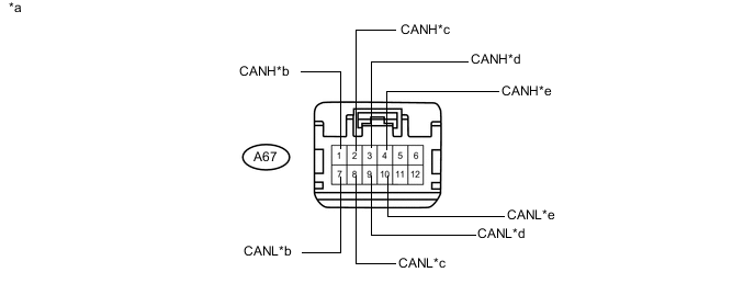
Text in Illustration *a Front view of wire harness connector
(to CAN No. 1 Junction Connector)
*b to ECM
(for V Bus)
*c to Brake Booster with Master Cylinder Assembly (Skid Control ECU)
(for V Bus)
*d to Brake Booster with Master Cylinder Assembly (Skid Control ECU)
(for Sub Bus 15)
*e to ECM
(for Sub Bus 15)
- - -
Check the connection diagram of the components which are connected to the CAN No. 1 junction connector.
Terminal No. (Symbol) Wiring Color Connected to A67-1 (CANH) P ECM
(for V bus)
A67-7 (CANL) V A67-2 (CANH) LG Brake booster with master cylinder assembly (Skid control ECU)
(for V bus)
A67-8 (CANL) L A67-3 (CANH) P Brake booster with master cylinder assembly (Skid control ECU)
(for Sub bus 15)
A67-9 (CANL) V A67-4 (CANH) B ECM
(for Sub bus 15)
A67-10 (CANL) W
-
-
Check the CAN No. 1 junction connector (instrument panel wire side).
-
Connection diagram
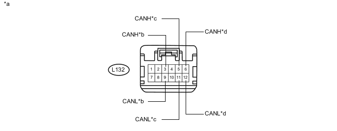
Text in Illustration *a Front view of wire harness connector
(to CAN No. 1 Junction Connector)
*b to CAN No. 5 Junction Connector
(for Sub Bus 15)
*c Main body ECU (Multiplex Network Body ECU)
(for V Bus)
*d to CAN No. 2 Junction Connector
(for V Bus)
-
Check the connection diagram of the components which are connected to the CAN No. 1 junction connector.
Terminal No. (Symbol) Wiring Color Connected to L132-3 (CANH) R CAN No. 5 junction connector
(for Sub bus 15)
L132-9 (CANL) Y L132-5 (CANH) SB Main body ECU (Multiplex network body ECU)
(for V bus)
L132-11 (CANL) W L132-6 (CANH) B CAN No. 2 junction connector
(for V bus)
L132-12 (CANL) W
-
-
-
CAN NO. 1 JUNCTION CONNECTOR (for RHD)
-
Check the CAN No. 1 junction connector (engine room main wire side).
-
Connection diagram
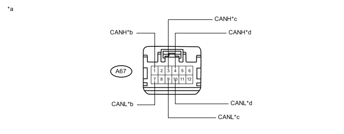
Text in Illustration *a Front view of wire harness connector
(to CAN No. 1 Junction Connector)
*b to Brake Booster with Master Cylinder Assembly (Skid Control ECU)
(for V Bus)
*c to Brake Booster with Master Cylinder Assembly (Skid Control ECU)
(for Sub Bus 15)
*d to ECM
(for Sub Bus 15)
-
Check the connection diagram of the components which are connected to the CAN No. 1 junction connector.
Terminal No. (Symbol) Wiring Color Connected to A67-1 (CANH) LG Brake booster with master cylinder assembly (Skid control ECU)
(for V bus)
A67-7 (CANL) L A67-3 (CANH) P Brake booster with master cylinder assembly (Skid control ECU)
(for Sub bus 15)
A67-9 (CANL) V A67-4 (CANH) B ECM
(for Sub bus 15)
A67-10 (CANL) W
-
-
Check the CAN No. 1 junction connector (instrument panel wire side).
-
Connection diagram
Text in Illustration *a Front view of wire harness connector
(to CAN No. 1 Junction Connector)
*b to CAN No. 5 Junction Connector
(for Sub Bus 15)
*c to CAN No. 2 Junction Connector
(for V Bus)
*d Combination Meter Sub-assembly
(for V Bus)
-
Check the connection diagram of the components which are connected to the CAN No. 1 junction connector.
Terminal No. (Symbol) Wiring Color Connected to L132-3 (CANH) R CAN No. 5 junction connector
(for Sub bus 15)
L132-9 (CANL) Y L132-5 (CANH) GR CAN No. 2 junction connector
(for V bus)
L132-11 (CANL) W L132-6 (CANH) SB Combination meter sub-assembly
(for V bus)
L132-12 (CANL) G
-
-
-
CAN NO. 2 JUNCTION CONNECTOR (for LHD)
-
Check the CAN No. 2 junction connector (instrument panel connector holder left side).
-
Connection diagram
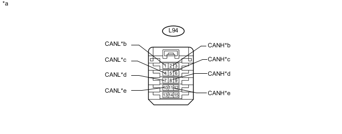
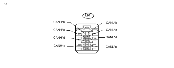
Text in Illustration *a Front view of wire harness connector
(to CAN No. 2 Junction Connector)
*b to CAN No. 3 Junction Connector
(for V Bus)
*c to CAN No. 1 Junction Connector
(for V Bus)
*d to Certification ECU (Smart Key ECU Assembly)
(for V Bus)
*e to Spiral Cable with Sensor Sub-assembly (Steering Angle Sensor)
(for V Bus)
- - -
Check the connection diagram of the components which are connected to the CAN No. 2 junction connector.
Terminal No. (Symbol) Wiring Color Connected to L94-2 (CANH) GR CAN No. 3 junction connector
(for V bus)
L94-1 (CANL) W L94-5 (CANH) B CAN No. 1 junction connector
(for V bus)
L94-4 (CANL) W L94-8 (CANH) B Certification ECU (Smart key ECU assembly)
(for V bus)
L94-7 (CANL) W L94-11 (CANH) B Spiral cable with sensor sub-assembly (Steering angle sensor)
(for V bus)
L94-10 (CANL) W
-
-
Check the CAN No. 2 junction connector (instrument panel connector holder right side).
-
Connection diagram
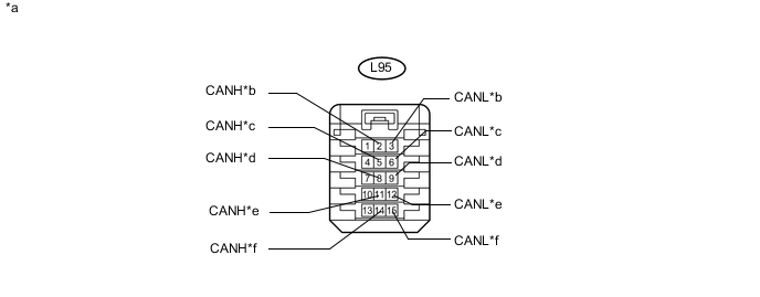
Text in Illustration *a Front view of wire harness connector
(to CAN No. 2 Junction Connector)
*b to Power Steering ECU Assembly
(for V Bus)
*c to Air Conditioning Amplifier Assembly
(for V Bus)
*d to Airbag ECU Assembly
(for V Bus)
*e to Radio and Display Receiver Assembly
(for Radio and Display Type)
(for V Bus)
*f to DLC3
(for V Bus)
-
Check the connection diagram of the components which are connected to the CAN No. 2 junction connector.
Terminal No. (Symbol) Wiring Color Connected to L95-2 (CANH) R Power steering ECU assembly
(for V bus)
L95-3 (CANL) W L95-5 (CANH) B Air conditioning amplifier assembly
(for V bus)
L95-6 (CANL) W L95-8 (CANH) B Airbag ECU assembly
(for V bus)
L95-9 (CANL) W L95-11 (CANH) L Radio and display receiver assembly*
(for V bus)
L95-12 (CANL) W L95-14 (CANH) G DLC3
(for V bus)
L95-15 (CANL) W *: for Radio and Display Type
-
-
-
CAN NO. 2 JUNCTION CONNECTOR (for RHD)
-
Check the CAN No. 2 junction connector (instrument panel connector holder left side).
-
Connection diagram
Text in Illustration *a Front view of wire harness connector
(to CAN No. 2 Junction Connector)
*b to CAN No. 1 Junction Connector
(for V Bus)
*c to CAN No. 3 Junction Connector
(for V Bus)
*d to Certification ECU (Smart Key ECU Assembly)
(for V Bus)
*e to Spiral Cable with Sensor Sub-assembly (Steering Angle Sensor)
(for V Bus)
- - -
Check the connection diagram of the components which are connected to the CAN No. 2 junction connector.
Terminal No. (Symbol) Wiring Color Connected to L94-1 (CANH) GR CAN No. 1 junction connector
(for V bus)
L94-2 (CANL) W L94-4 (CANH) B CAN No. 3 junction connector
(for V bus)
L94-5 (CANL) W L94-7 (CANH) B Certification ECU (Smart key ECU assembly)
(for V bus)
L94-8 (CANL) W L94-10 (CANH) B Spiral cable with sensor sub-assembly (Steering angle sensor)
(for V bus)
L94-11 (CANL) W
-
-
Check the CAN No. 2 junction connector (instrument panel connector holder right side).
-
Connection diagram
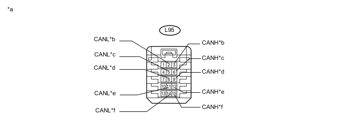
Text in Illustration *a Front view of wire harness connector
(to CAN No. 2 Junction Connector)
*b to Power Steering ECU Assembly
(for V Bus)
*c to Air Conditioning Amplifier Assembly
(for V Bus)
*d to Airbag ECU Assembly
(for V Bus)
*e
-
to Navigation Receiver Assembly
(for Navigation Receiver Type)
-
to Radio and Display Receiver Assembly
(for Radio and Display Type)
(for V Bus)
*f to DLC3
(for V Bus)
-
-
Check the connection diagram of the components which are connected to the CAN No. 2 junction connector.
Terminal No. (Symbol) Wiring Color Connected to L95-3 (CANH) R Power steering ECU assembly
(for V bus)
L95-2 (CANL) W L95-6 (CANH) B Air conditioning amplifier assembly
(for V bus)
L95-5 (CANL) W L95-9 (CANH) B Airbag ECU assembly
(for V bus)
L95-8 (CANL) W L95-12 (CANH) L
-
Navigation receiver assembly*1
-
Radio and display receiver assembly*2
(for V bus)
L95-11 (CANL) W L95-15 (CANH) G DLC3
(for V bus)
L95-14 (CANL) W *1: for Navigation Receiver Type
*2: for Radio and Display Type
-
-
-
-
CAN NO. 3 JUNCTION CONNECTOR (for LHD)
-
Check the CAN No. 3 junction connector (engine room main wire side).
-
Connection diagram
Text in Illustration *a Front view of wire harness connector
(to CAN No. 3 Junction Connector)
*b to Transmission Control ECU Assembly
(for V Bus)
-
Check the connection diagram of the components which are connected to the CAN No. 3 junction connector.
Terminal No. (Symbol) Wiring Color Connected to A68-1 (CANH) Y Transmission control ECU assembly
(for V bus)
A68-7 (CANL) BR
-
-
Check the CAN No. 3 junction connector (instrument panel wire side).
-
Connection diagram
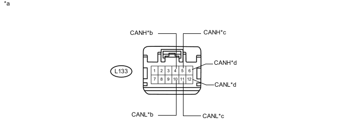
Text in Illustration *a Front view of wire harness connector
(to CAN No. 3 Junction Connector)
*b to Hybrid Vehicle Control ECU
(for V Bus)
*c to CAN No. 2 Junction Connector
(for V Bus)
*d to Combination Meter Sub-assembly
(for V Bus)
-
Check the connection diagram of the components which are connected to the CAN No. 3 junction connector.
Terminal No. (Symbol) Wiring Color Connected to L133-4 (CANH) V Hybrid vehicle control ECU
(for V bus)
L133-10 (CANL) P L133-5 (CANH) GR CAN No. 2 junction connector
(for V bus)
L133-11 (CANL) W L133-6 (CANH) SB Combination meter sub-assembly
(for V bus)
L133-12 (CANL) G
-
-
-
CAN NO. 3 JUNCTION CONNECTOR (for RHD)
-
Check the CAN No. 3 junction connector (engine room main wire side).
-
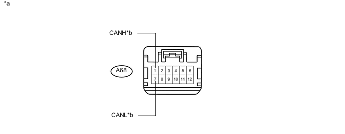
Connection diagram
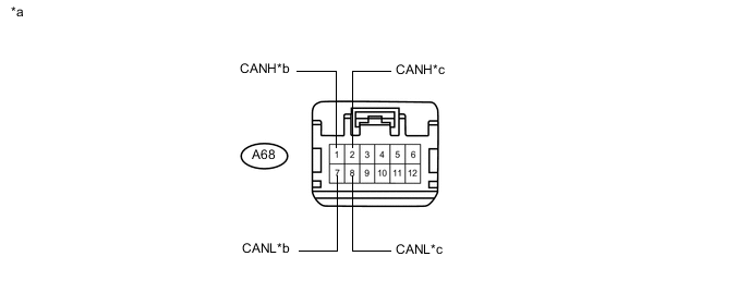
Text in Illustration *a Front view of wire harness connector
(to CAN No. 3 Junction Connector)
*b ECM
(for V Bus)
*c to Transmission Control ECU Assembly
(for V Bus)
- - -
Check the connection diagram of the components which are connected to the CAN No. 3 junction connector.
Terminal No. (Symbol) Wiring Color Connected to A68-1 (CANH) P ECM
(for V bus)
A68-7 (CANL) V A68-2 (CANH) Y Transmission control ECU assembly
(for V bus)
A68-8 (CANL) BR
-
-
Check the CAN No. 3 junction connector (instrument panel wire side).
-
Connection diagram
Text in Illustration *a Front view of wire harness connector
(to CAN No. 3 Junction Connector)
*b to Hybrid Vehicle Control ECU
(for V Bus)
*c to Main body ECU (Multiplex Network Body ECU)
(for V Bus)
*d to CAN No. 2 Junction Connector
(for V Bus)
-
Check the connection diagram of the components which are connected to the CAN No. 3 junction connector.
Terminal No. (Symbol) Wiring Color Connected to L133-4 (CANH) V Hybrid vehicle control ECU
(for V bus)
L133-10 (CANL) P L133-5 (CANH) SB Main body ECU (Multiplex network body ECU)
(for V bus)
L133-11 (CANL) W L133-6 (CANH) B CAN No. 2 junction connector
(for V bus)
L133-12 (CANL) W
-
-
-
CAN NO. 5 JUNCTION CONNECTOR
-
Check the CAN No. 5 junction connector (instrument panel connector holder left side).
-
Connection diagram
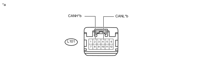
Text in Illustration *a Front view of wire harness connector
(to CAN No. 5 Junction Connector)
*b to CAN No. 1 Junction Connector
(for Sub Bus 15)
-
Check the connection diagram of the components which are connected to the CAN No. 5 junction connector.
Terminal No. (Symbol) Wiring Color Connected to L101-2 (CANH) R CAN No. 1 junction connector
(for Sub bus 15)
L101-4 (CANL) Y
-
-
Check the CAN No. 5 junction connector (instrument panel connector holder right side).
-
Connection diagram
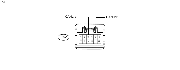
Text in Illustration *a Front view of wire harness connector
(to CAN No. 5 Junction Connector)
*b to Hybrid Vehicle Control ECU
(for Sub Bus 15)
-
Check the connection diagram of the components which are connected to the CAN No. 5 junction connector.
Terminal No. (Symbol) Wiring Color Connected to L102-5 (CANH) B Hybrid vehicle control ECU
(for Sub bus 15)
L102-3 (CANL) W
-
-
-
DLC3
-
Measure the resistance according to the value(s) in the table below.
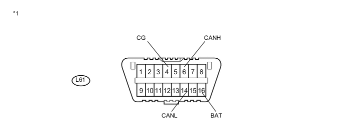
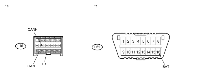
Text in Illustration *1 DLC3 - -
-
-
HYBRID VEHICLE CONTROL ECU
Text in Illustration *a Component without harness connected
(Hybrid Vehicle Control ECU)
- -
-
Disconnect the cable from the negative (-) auxiliary battery terminal.
-
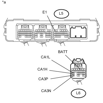
Text in Illustration *a Rear view of wire harness connector
(to Hybrid Vehicle Control ECU)
Disconnect the L6 hybrid vehicle control ECU connector.
-
Measure the resistance according to the value(s) in the table below.
-
-
ECM
Text in Illustration *a Component without harness connected
(ECM)
- -
-
Disconnect the cable from the negative (-) auxiliary battery terminal.
-
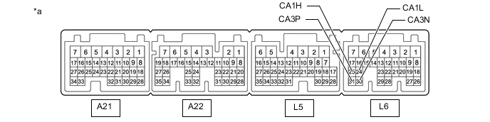
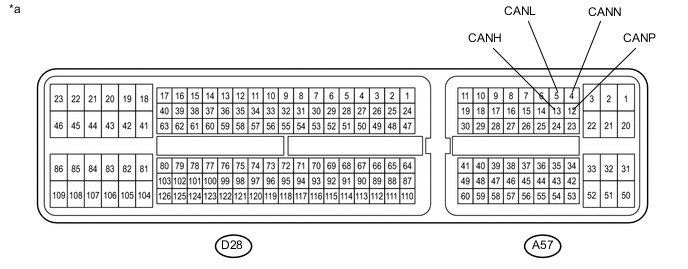
Disconnect the A57 and D28 ECM connectors.
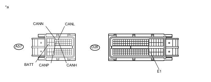
Text in Illustration *a Front view of wire harness connector
(to ECM)
- - -
Measure the resistance according to the value(s) in the table below.
-
-
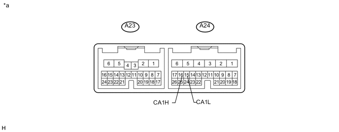
TRANSMISSION CONTROL ECU ASSEMBLY
Text in Illustration *a Component without harness connected
(Transmission Control ECU Assembly)
- -
-
Disconnect the cable from the negative (-) auxiliary battery terminal.
-
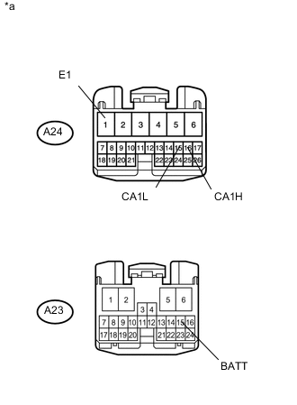
Text in Illustration *a Front view of wire harness connector
(to Transmission Control ECU Assembly)
Disconnect the A23 and A24 transmission control ECU assembly connectors.
-
Measure the resistance according to the value(s) in the table below.
-
-
BRAKE BOOSTER WITH MASTER CYLINDER ASSEMBLY (SKID CONTROL ECU)
-
Disconnect the cable from the negative (-) auxiliary battery terminal.
-
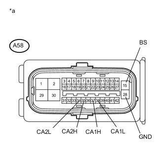
Text in Illustration *a Front view of wire harness connector
(to Brake Booster with Master Cylinder Assembly (Skid Control ECU))
Disconnect the A58 brake booster with master cylinder assembly (skid control ECU) connector.
-
Measure the resistance according to the value(s) in the table below.
-
-
AIRBAG ECU ASSEMBLY
Text in Illustration *a Component without harness connected
(Airbag ECU Assembly)
- -
-
Disconnect the cable from the negative (-) auxiliary battery terminal.
-
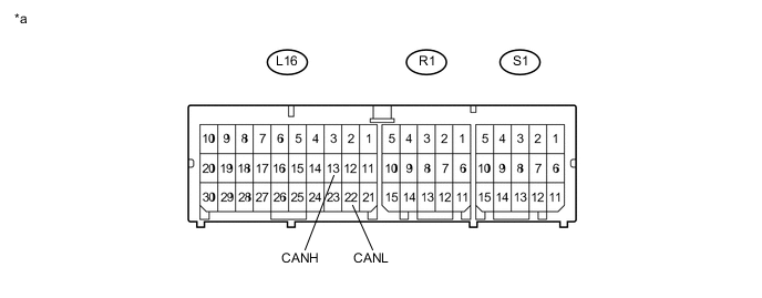
Disconnect the L16 airbag ECU assembly connector.
Text in Illustration *1 DLC3 - - *a Front view of wire harness connector
(to Airbag ECU Assembly)
- - -
Measure the resistance according to the value(s) in the table below.
-
-
INSTRUMENT PANEL JUNCTION BLOCK ASSEMBLY AND MAIN BODY ECU (MULTIPLEX NETWORK BODY ECU)
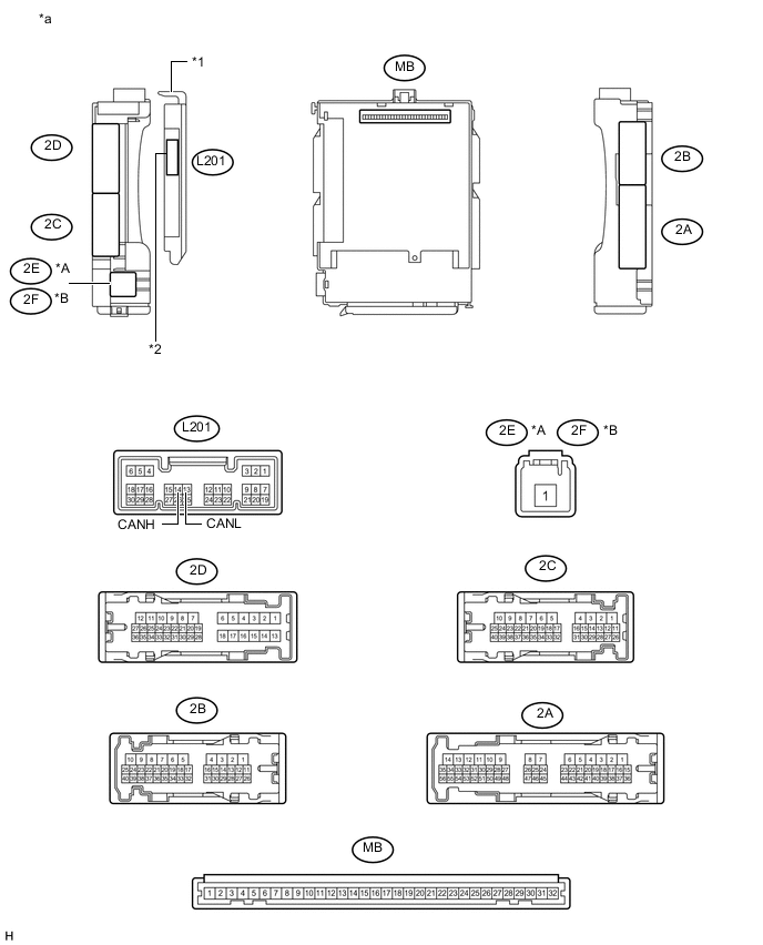
Text in Illustration *A for LHD *B for RHD *1 Main Body ECU (Multiplex Network Body ECU) *2 1 connector *a Component without harness connected
(Instrument Panel Junction Block Assembly and Main Body ECU (Multiplex Network Body ECU))
- - 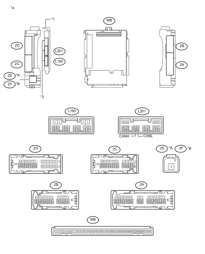
Text in Illustration *A for LHD *B for RHD *1 Main Body ECU (Multiplex Network Body ECU) *2 3 connectors *a Component without harness connected
(Instrument Panel Junction Block Assembly and Main Body ECU (Multiplex Network Body ECU))
- -
-
Disconnect the cable from the negative (-) auxiliary battery terminal.
-
Disconnect the L201 main body ECU (multiplex network body ECU) connector.
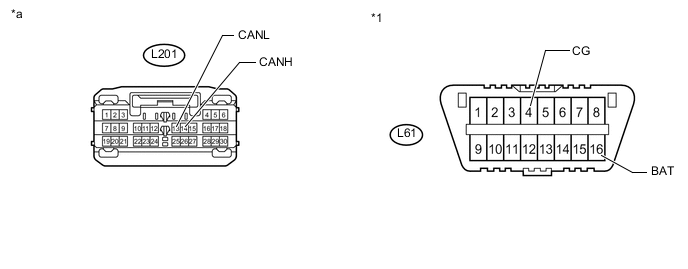
Text in Illustration *1 DLC3 - - *a Front view of wire harness connector
(to Main Body ECU (Multiplex Network Body ECU))
- - -
Measure the resistance according to the value(s) in the table below.
-
-
SPIRAL CABLE WITH SENSOR SUB-ASSEMBLY (STEERING ANGLE SENSOR)
-
Disconnect the cable from the negative (-) auxiliary battery terminal.
-
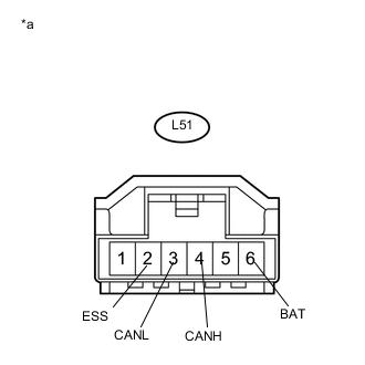
Text in Illustration *a Front view of wire harness connector
(to Spiral Cable with Sensor Sub-assembly (Steering Angle Sensor))
Disconnect the L51 spiral cable with sensor sub-assembly (steering angle sensor) connector.
-
Measure the resistance according to the value(s) in the table below.
-
-
POWER STEERING ECU ASSEMBLY
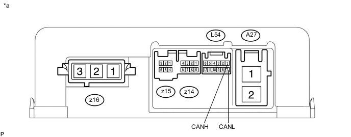
Text in Illustration *a Component without harness connected
(Power Steering ECU Assembly)
- -
-
Disconnect the cable from the negative (-) auxiliary battery terminal.
-
Disconnect the A27 and L54 power steering ECU assembly connectors.
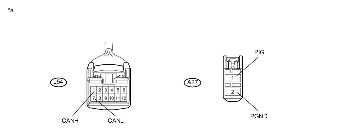
Text in Illustration *a Front view of wire harness connector
(to Power Steering ECU Assembly)
- - -
Measure the resistance according to the value(s) in the table below.
-
-
CERTIFICATION ECU (SMART KEY ECU ASSEMBLY)
Text in Illustration *a Component without harness connected
(Certification ECU (Smart Key ECU Assembly))
- -
-
Disconnect the cable from the negative (-) auxiliary battery terminal.
-
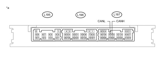
Disconnect the L195 and L197 certification ECU (smart key ECU assembly) connectors.
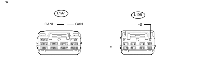
Text in Illustration *a Front view of wire harness connector
(to Certification ECU (Smart Key ECU Assembly))
- - -
Measure the resistance according to the value(s) in the table below.
-
-
RADIO AND DISPLAY RECEIVER ASSEMBLY (for Radio and Display Type)
Text in Illustration *a Component without harness connected
(Radio and Display Receiver Assembly)
- -
-
Disconnect the cable from the negative (-) auxiliary battery terminal.
-
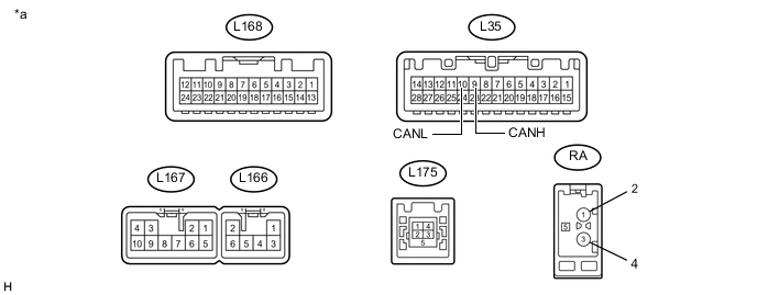
Disconnect the L35 and L167 radio and display receiver assembly connectors.
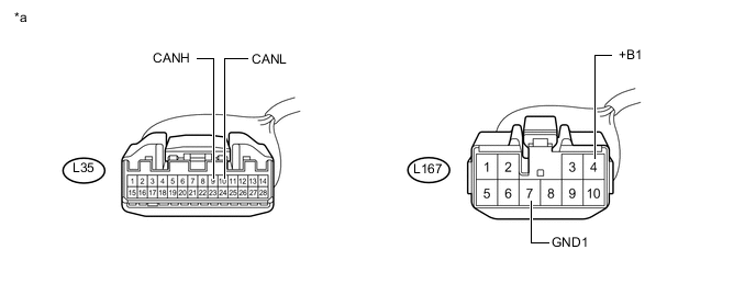
Text in Illustration *a Front view of wire harness connector
(to Radio and Display Receiver Assembly)
- - -
Measure the resistance according to the value(s) in the table below.
-
-
NAVIGATION RECEIVER ASSEMBLY (for Navigation Receiver Type)

Text in Illustration *a Component without harness connected
(Navigation Receiver Assembly)
- -
-
Disconnect the cable from the negative (-) auxiliary battery terminal.
-
Disconnect the L38 and L171 navigation receiver assembly connectors.
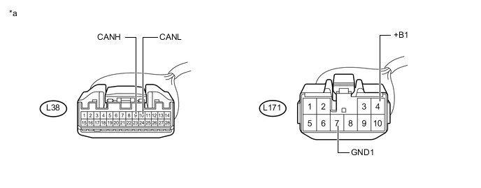
Text in Illustration *a Front view of wire harness connector
(to Navigation Receiver Assembly)
- - -
Measure the resistance according to the value(s) in the table below.
-
-
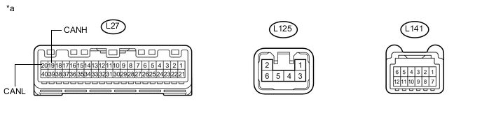
COMBINATION METER SUB-ASSEMBLY
Text in Illustration *a Component without harness connected
(Combination Meter Sub-assembly)
- -
-
Disconnect the cable from the negative (-) auxiliary battery terminal.
-
Disconnect the L27 combination meter sub-assembly connector.
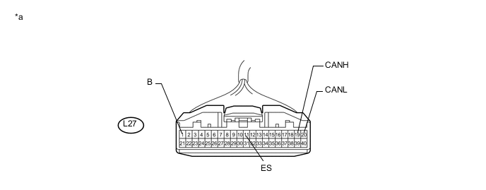
Text in Illustration *a Front view of wire harness connector
(to Combination Meter Sub-assembly)
- - -
Measure the resistance according to the value(s) in the table below.
-
-
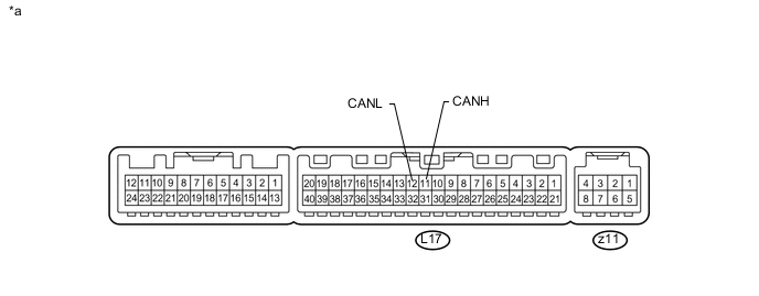
AIR CONDITIONING AMPLIFIER ASSEMBLY
Text in Illustration *a Component without harness connected
(Air Conditioning Amplifier Assembly)
- -
-
Disconnect the cable from the negative (-) auxiliary battery terminal.
-
Disconnect the L17 air conditioning amplifier assembly connector.
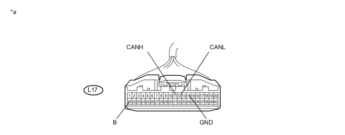
Text in Illustration *a Front view of wire harness connector
(to Air Conditioning Amplifier Assembly)
- - -
Measure the resistance according to the value(s) in the table below.
-