UPPER INSTRUMENT PANEL INSTALLATION
PROCEDURE
INSTALL UPPER INSTRUMENT PANEL ASSEMBLY
Push the upper instrument panel assembly in the direction indicated by the arrow (1) to engage the 5 guides.
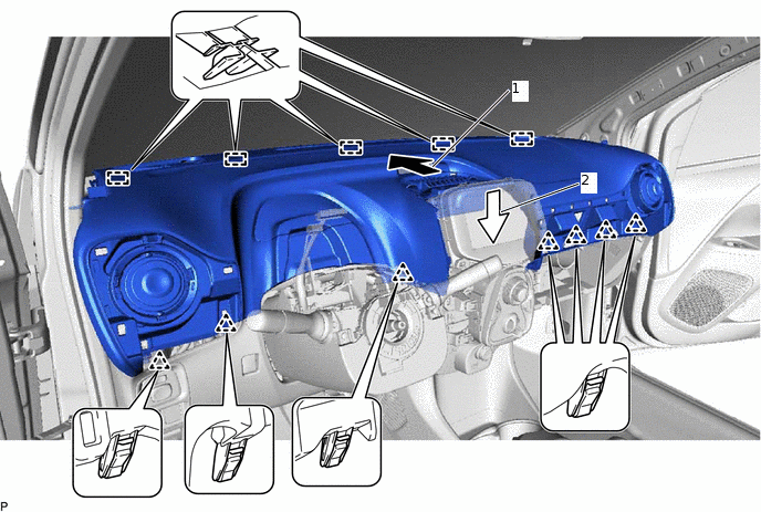
Push the upper instrument panel assembly in the direction indicated by the arrow (2) to engage the 7 clips and install the upper instrument panel assembly.
Install the bolt <A>.
18 N*m
184 kgf*cm
13 ft.*lbf
Install the 2 screws <B> and 2 clips.
Connect the connector.
CONNECT INSTRUMENT PANEL PASSENGER AIRBAG CONNECTOR
INSTALL NO. 2 INSTRUMENT PANEL SPEAKER PANEL SUB-ASSEMBLY
Connect the connector.
-
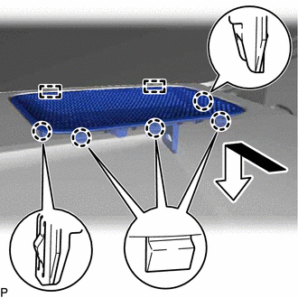
Engage the 2 guides and 5 claws as shown in the illustration to install the No. 2 instrument panel speaker panel sub-assembly.
INSTALL FRONT PILLAR GARNISH RH
INSTALL FRONT DOOR OPENING TRIM WEATHERSTRIP RH
for 5 Door:Click here
for 3 Door:Click hereClick here
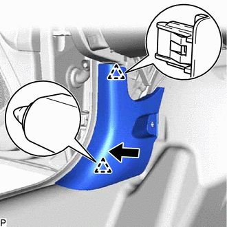
INSTALL COWL SIDE TRIM BOARD RH
-
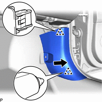
Engage the 2 clips as shown in the illustration.
Install the cowl side trim board RH with the clip.
-
INSTALL NO. 1 INSTRUMENT PANEL SPEAKER PANEL SUB-ASSEMBLY
Connect the connector.
-
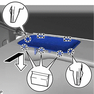
Engage the 2 guides and 5 claws as shown in the illustration to install the No. 1 instrument panel speaker panel sub-assembly.
INSTALL FRONT PILLAR GARNISH LH
INSTALL FRONT DOOR OPENING TRIM WEATHERSTRIP LH
for 5 Door:Click here
for 3 Door:Click hereClick here
INSTALL COWL SIDE TRIM SUB-ASSEMBLY LH
-
Engage the 2 clips as shown in the illustration.
Install the cowl side trim sub-assembly LH with the clip.
-
INSTALL NO. 2 INSTRUMENT PANEL GARNISH SUB-ASSEMBLY
Engage the 13 clips to install the No. 2 instrument panel garnish sub-assembly.
INSTALL GLOVE COMPARTMENT DOOR ASSEMBLY
-
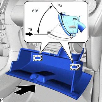
*a
Opened Approximately 60°
*b
Closed
With the glove compartment door assembly opened approximately 60° from its closed position, push it in horizontally and engage the 2 hinges.
Note:Engaging the hinges from the top will deform the hinges. Be sure to install the glove compartment door assembly horizontally.
-
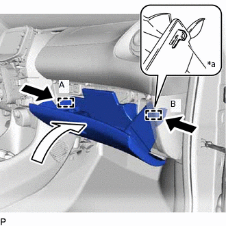
*a
Stopper
Slightly push in the stoppers (A) and (B) in the directions indicated by the arrows in the illustration and engage the stoppers to install the glove compartment door assembly.
-
INSTALL INSTRUMENT CLUSTER FINISH PANEL SUB-ASSEMBLY
-
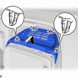
Engage the 2 guides and 2 clips as shown in the illustration to install the instrument cluster finish panel sub-assembly.
-
INSTALL CENTER INSTRUMENT CLUSTER FINISH PANEL SUB-ASSEMBLY
Connect each connector.
Engage the 2 claws and 10 clips to install the center instrument cluster finish panel sub-assembly.
INSTALL NO. 1 INSTRUMENT PANEL GARNISH SUB-ASSEMBLY
Engage the 6 clips to install the No. 1 instrument panel garnish sub-assembly.
INSTALL COMBINATION METER ASSEMBLY