СИСТЕМА SFI, Diagnostic DTC:P1613
| DTC Code | DTC Name |
|---|---|
| P1613 | Secondary Air Injection Driver Malfunction |
DESCRIPTION
Refer to DTC P0412 Click here.
| DTC No. | DTC Detection Conditions | Trouble Areas |
|---|---|---|
| P1613 | Either (a) or (b) is met (a) All conditions below are met (1 trip detection logic):
(b) All conditions below are met (1 trip detection logic):
|
|
| P1613 | All conditions below are met (1 trip detection logic): (a) Air injection system is operating (b) Diagnostic signal from AID is 0% (c) Battery voltage is 8 V or more |
|
| P1613 | All conditions below are met (1 trip detection logic): (a) Battery voltage is 8 V or more (b) Diagnostic signal from AID is 100% |
|
MONITOR DESCRIPTION
When a cold engine is started, the ECM immediately transmits command signals to the AID to drive the air pump and ASV. AID detects an open or short in the air pump and ASV circuit according to the AID terminal voltage and sends a signal as the diagnostic information to the ECM.
If the Secondary Air Injection (AI) system circuit or the AID itself has a malfunction, the AID sends a malfunction signal (duty signal) as a diagnostic signal to the ECM (when the system is normal, a system normal signal is sent). The ECM sets the DTC based on the diagnostic information from the AID.
Example:
-
The duty ratio of the diagnostic signal from AID is 0 or 100% (remains at 0 V or battery voltage).
-
The duty ratio of the diagnostic signal from AID is not 0, 20, 40, 80, or 100%.
-
The AID outputs the normal signal (normal duty signal: 80%) while the system not operating.
WIRING DIAGRAM
Refer to DTC P0412 Click here.
INSPECTION PROCEDURE
Tech Tips
The diagnostic information output from the AID can be confirmed by connecting an oscilloscope to the diagnostic information terminal of the AID.
-
-
Connect the intelligent tester to the DLC3.
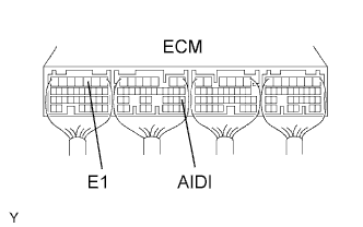
-
Connect an oscilloscope probe to the AIDI terminal of the ECM.
-
Start the engine and turn the tester ON.
-
On the tester, select the following menu items: Powertrain / Engine and ECT / Data List.
-
Monitor the output voltage of the AID (duty ratio signal).
| Oscilloscope range | ||||||||
|---|---|---|---|---|---|---|---|---|
|
| AID Diagnostic Signal Waveform | ECM Command | DTC (ECM Output) |
Suspected Trouble Area |
|---|---|---|---|
| 100% Duty Ratio See waveform 1 |
Any Air Injection (AI) System operation | P1613 |
|
| 0% Duty Ratio See waveform 2 |
AI System: ON (Air pump ON, ASV ON) |
P1613 |
|
| AI System: OFF (Air pump OFF, ASV OFF) |
- |
|
|
| 20% Duty Ratio See waveform 3 |
Air Pump: ON | P0418 |
|
| Air Pump: OFF | P0418 |
|
|
| 40% Duty Ratio See waveform 4 |
ASV: ON | P0412 |
|
| ASV: OFF | P0412 |
|
|
| 80% Duty Ratio See waveform 5 |
AI System: OFF (Air pump OFF, ASV OFF) |
P1613 |
|
| AI System: ON (Air pump ON, ASV ON) |
- |
|
|
| Excluding Above (excluding 0, 20, 40, 80, 100% duty) |
- | P1613 |
|
-
Waveform 1
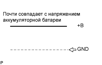
-
100% Duty Ratio
-
-
Waveform 2
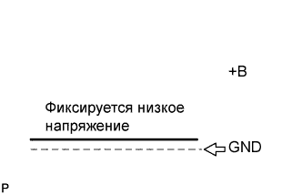
-
0% Duty Ratio
-
-
Waveform 3
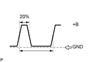
-
20% Duty Ratio
-
-
Waveform 4
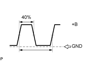
-
40% Duty Ratio
-
-
Waveform 5
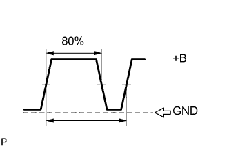
-
80% Duty Ratio
Tech Tips
Read freeze frame data using the intelligent tester. Freeze frame data records the engine conditions when malfunctions are detected. When troubleshooting, freeze frame data can help determine if the vehicle was moving or stationary, if the engine was warmed up or not, if the air-fuel ratio was lean or rich, and other data from the time the malfunction occurred.
-
PROCEDURE
-
CHECK OTHER DTC OUTPUT (IN ADDITION TO AIR INJECTION SYSTEM DTCS)
-
Connect the intelligent tester to the DLC3.
-
Turn the ignition switch ON and turn the tester ON.
-
Select the following menu items: Powertrain / Engine and ECT / DTC.
-
Read DTCs.
Result Display (DTC output) Proceed to P1613 A P1613 and other DTCs. B Tech Tips
If any DTCs other than P1613 are output, troubleshoot those DTCs first.
B 
GO TO RELEVANT DTC CHART
A 
-
-
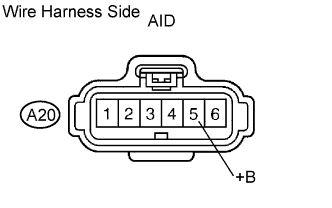
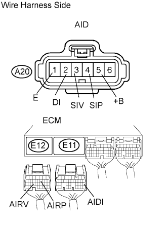
CHECK AIR INJECTION CONTROL DRIVER (POWER SOURCE)
-
Disconnect the A20 AID connector.
-
Turn the ignition switch ON.
-
Measure the voltage of the wire harness side connector.
Standard voltage Tester Connection Specified Condition A20-5 (+B) - Body ground 9 to 14 V
NG
REPAIR OR REPLACE HARNESS AND CONNECTOR
OK
-
-
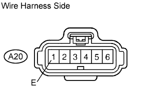
CHECK WIRE HARNESS (AIR INJECTION CONTROL DERIVER - BODY GROUND)
-
Disconnect the A20 AID connector.
-
Measure the resistance of the wire harness side connector.
Standard resistance Tester Connection Specified Condition A20-1 (E) - Body ground Below 1 Ω
NG
REPAIR OR REPLACE HARNESS AND CONNECTOR
OK
-
-
CHECK WIRE HARNESS (AIR INJECTION CONTROL DRIVER - ECM)
-
Disconnect the A20 AID connector.
-
Disconnect the E11 and E12 ECM connectors.
-
Measure the resistance of the wire harness side connectors.
Standard resistance Tester Connection Specified Condition A20-2 (DI) - E11-20 (AIDI) Below 1 Ω A20-4 (SIP) - E12-11 (AIRP) Below 1 Ω A20-3 (SIV) - E12-24 (AIRV) Below 1 Ω A20-2 (DI) or E11-20 (AIDI) - A20-5 (+B) 10 kΩ or higher
NG
REPAIR OR REPLACE HARNESS AND CONNECTOR
OK
-
-
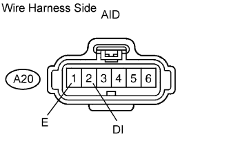
CHECK AIR INJECTION CONTROL DRIVER
-
Disconnect the A20 AID connector.
-
Turn the ignition switch ON.
-
Measure the voltage of the wire harness side connector.
Standard voltage Tester Connection Specified Condition A20-2 (DI) - A20-1 (E) 9 to 14 V
NG
REPLACE ECM
OK 
REPLACE AIR INJECTION CONTROL DRIVER
-