UPPER INSTRUMENT PANEL INSTALLATION
PROCEDURE
-
INSTALL UPPER INSTRUMENT PANEL ASSEMBLY
-
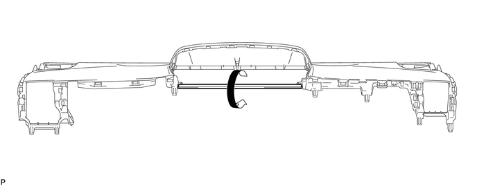
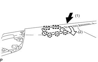
When using a new upper instrument panel sub-assembly:
-
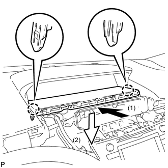
Immediately before installing the upper instrument panel assembly, twist and cut off the portion shown in the illustration.
-
-
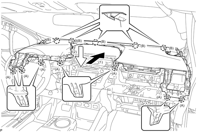
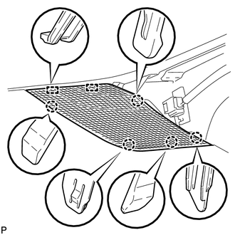
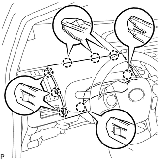
Engage the 5 claws (B) as shown in the illustration.
-
Engage the 7 claws (A) as shown in the illustration.
Note
-
Do not damage the upper instrument panel assembly.
-
Do not allow the wire harnesses to interfere with the surrounding parts.
-
-
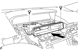
Install the 2 bolts <A>.
-
Install the 2 passenger airbag bolts <B>.
- Torque:
- 20 N*m { 204 kgf*cm, 15 ft.*lbf }
-
Connect the connector to install the upper instrument panel assembly.
-
-
CONNECT NO. 3 INSTRUMENT PANEL WIRE
-
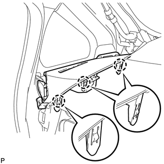
INSTALL INSTRUMENT CLUSTER FINISH PANEL END (w/ Headup Display)
-
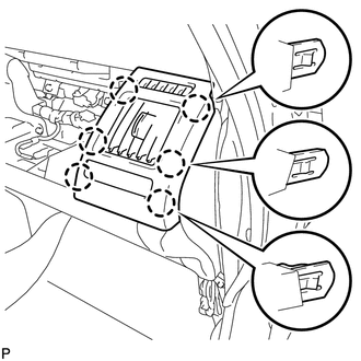
Engage the 2 guides and 5 claws to install the instrument cluster finish panel end as shown in the illustration.
-
-
INSTALL INSTRUMENT CLUSTER FINISH PANEL SUB-ASSEMBLY
-
Engage the 3 guide and 2 clips.
-
Install the instrument cluster finish panel sub-assembly with the 2 screws <D> and 3 clips.
-
-
INSTALL NO. 2 HEATER TO REGISTER DUCT SUB-ASSEMBLY
-
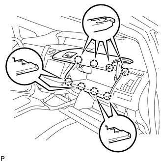
Engage the 2 guides as shown in the illustration.
-
Install the No. 2 heater to register duct sub-assembly with the 2 clips.
-
-
INSTALL LOWER CENTER INSTRUMENT CLUSTER FINISH PANEL SUB-ASSEMBLY
-
Engage the 2 claws to install the lower center instrument cluster finish panel sub-assembly as shown in the illustration.
-
-
INSTALL CENTER INSTRUMENT PANEL REGISTER ASSEMBLY
-
Engage the 8 claws to install the center instrument panel register assembly.
-
-
INSTALL FRONT NO. 2 SPEAKER ASSEMBLY
Tech Tips
Use the same procedure as for the LH side Click here.
-
INSTALL NO. 2 INSTRUMENT PANEL SPEAKER PANEL SUB-ASSEMBLY
-
Engage the 2 guides and 5 claws to install the No. 2 instrument panel speaker panel sub-assembly.
-
-
INSTALL LOWER FRONT PILLAR GARNISH RH
-
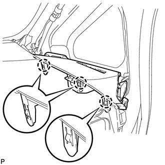
Engage the 3 claws to install the lower front pillar garnish RH.
-
-
INSTALL FRONT PILLAR GARNISH RH
Tech Tips
Use the same procedure as for the LH side Click here
-
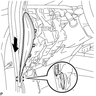
INSTALL INSTRUMENT PANEL FINISH PANEL END RH
-
Connect the connector.
-
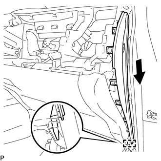
Engage the guide as shown in the illustration.
-
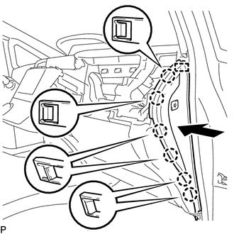
Engage the guide and 6 claws to install the instrument panel finish panel end RH as shown in the illustration.
-
-
INSTALL FRONT DOOR OPENING TRIM WEATHERSTRIP RH
-
INSTALL INSTRUMENT PANEL CUP HOLDER
-
Install the instrument panel cup holder with the 2 screws <E>.
-
-
INSTALL NO. 2 INSTRUMENT PANEL REGISTER ASSEMBLY
-
Engage the 6 claws.
-
Install the No. 2 instrument panel register assembly with the screw <C>.
-
-
INSTALL INSTRUMENT PANEL BOX ASSEMBLY
-
Open the instrument panel box and glove compartment door.
-
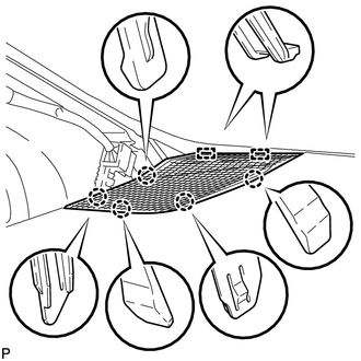
Engage the 8 claws to install the instrument panel box assembly.
-
Close the instrument panel box and glove compartment door.
-
-
INSTALL FRONT NO. 2 SPEAKER ASSEMBLY
-
INSTALL NO. 1 INSTRUMENT PANEL SPEAKER PANEL SUB-ASSEMBLY
-
Engage the 2 guides and 5 claws to install the No. 1 instrument panel speaker panel sub-assembly.
-
-
INSTALL LOWER FRONT PILLAR GARNISH LH
-
Engage the 3 claws to install the lower front pillar garnish LH.
-
-
INSTALL FRONT PILLAR GARNISH LH
-
INSTALL INSTRUMENT PANEL FINISH PANEL END LH
-
Engage the guide as shown in the illustration.
-
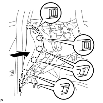
Engage the guide and 6 claws to install the instrument panel finish panel end LH as shown in the illustration.
-
-
INSTALL FRONT DOOR OPENING TRIM WEATHERSTRIP LH
-
INSTALL NO. 1 INSTRUMENT PANEL REGISTER ASSEMBLY
-
w/ Headup display:
-
Connect the connector.
-
-
Engage the 6 claws to install the No. 1 instrument panel register assembly.
-
-
INSTALL UPPER INSTRUMENT PANEL FINISH PANEL SUB-ASSEMBLY
-
Engage the 8 claws to install the upper instrument panel finish panel sub-assembly.
-
-
INSTALL LOWER INSTRUMENT PANEL FINISH PANEL ASSEMBLY
-
Engage each connector.
-
Engage the 8 claws and clip to install the lower instrument panel finish panel assembly.
-
-
INSTALL UPPER INSTRUMENT PANEL FINISH PANEL
-
Engage the 2 claws and clip to install the upper instrument panel finish panel.
-
-
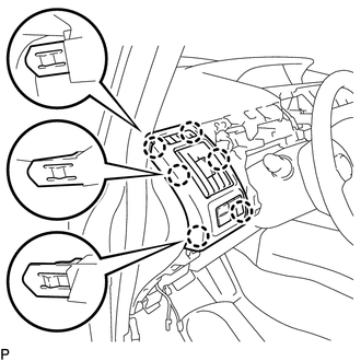
INSTALL INTEGRATION CONTROL AND PANEL
-
Engage each connector.
-
Engage the 8 claws to install the integration control and panel.
-
-
CONNECT CABLE TO NEGATIVE AUXILIARY BATTERY TERMINAL
Note
When disconnecting the cable, some systems need to be initialized after the cable is reconnected Click here.
-
INSTALL DECK FLOOR BOX RH
-
INSTALL REAR DECK FLOOR BOX
-
INSTALL NO. 1 DECK BOARD
-
INSTALL NO. 2 DECK BOARD
-
INSTALL DECK BOARD ASSEMBLY
-
INSPECT SRS WARNING LIGHT