ENGINE UNIT REMOVAL

CAUTION / NOTICE / HINT
The necessary procedures (adjustment, calibration, initialization, or registration) that must be performed after parts are removed and installed, or replaced during engine unit removal/installation are shown below.
| Replaced Part or Performed Procedure | Necessary Procedure | Effect/Inoperative Function when Necessary Procedure not Performed | Link | |
|---|---|---|---|---|
| Battery terminal is disconnected/reconnected | Perform steering sensor zero point calibration | Lane departure alert system (w/ Steering Control) | ||
| Pre-collision system | ||||
| Memorize steering angle neutral point | Parking assist monitor system | |||
| Panoramic view monitor system | ||||
| Replacement of ECM | Vehicle Identification Number (VIN) registration | MIL comes on | ||
| Perform code registration (Immobiliser system) | Engine start function | See Service Bulletin for the registration method. | ||
|
Inspection after repair |
|
||
| Replacement of automatic transaxle assembly | Perform the following procedures in the order shown:
|
|
Click here for U761E Initialization Click here for U761E Registration |
|
| Replacement of ECM (If possible, read the transaxle compensation code from the previous ECM) |
Possible | Perform the following procedures in the order shown:
|
||
| Impossible | Perform the following procedures in the order shown:
|
|||
| Replacement of ECM | Perform code registration (Immobiliser function) |
|
See Service Bulletin for the registration method. | |
| Suspension, tires, etc.*1 | Rear television camera assembly optical axis (Back camera position setting) | Parking assist monitor system | Click here for Initialization Click here for Calibration |
|
|
Panoramic view monitor system | Click here for Initialization Click here for Calibration |
||
| Replacement of front bumper assembly | Front television camera view adjustment | |||
| Front wheel alignment adjustment | Perform system variant learning and acceleration sensor zero point calibration. |
|
||
PROCEDURE
-
REMOVE ENGINE OIL LEVEL DIPSTICK GUIDE
-
Remove the engine oil level dipstick.
-
Remove the bolt and engine oil level dipstick guide.
-
Remove the O-ring from the engine oil level dipstick guide.
-
-
REMOVE NO. 1 EXHAUST MANIFOLD HEAT INSULATOR
-
REMOVE EGR PIPE CONNECTOR
-
REMOVE MANIFOLD STAY
-
REMOVE NO. 2 MANIFOLD STAY
-
REMOVE EXHAUST MANIFOLD CONVERTER SUB-ASSEMBLY (TWC: Front Catalyst)
-
REMOVE V-RIBBED BELT
-
REMOVE GENERATOR ASSEMBLY
-
REMOVE WIRE HARNESS CLAMP BRACKET
-
Remove the bolt and wire harness clamp bracket.
-
Remove the bolt and wire harness clamp bracket.
-
Remove the bolt and wire harness clamp bracket.
-
Remove the bolt and wire harness clamp bracket.
-
-
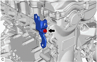
REMOVE WIRE HARNESS CLAMP BRACKET
-
REMOVE COMPRESSOR ASSEMBLY WITH MAGNETIC CLUTCH
-
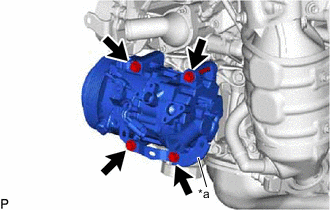
for Type A:
-
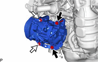
*a Bracket 
Bolt 
Nut Remove the 2 bolts and 2 nuts, and separate the bracket.
-
Using an E8 "TORX" socket wrench, remove the 2 stud bolts.
-
-
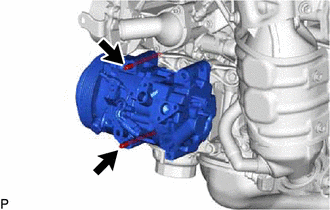
for Type B:
-
*a Bracket Remove the 4 bolts and separate the bracket.
-
-
Remove the compressor assembly with magnetic clutch.
-
-
REMOVE DRIVE SHAFT BEARING BRACKET
-
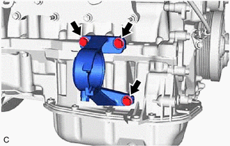
Remove the 3 bolts and drive shaft bearing bracket.
-
-
REMOVE NO. 1 COMPRESSOR MOUNTING BRACKET
-
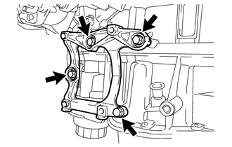
Remove the 4 bolts and No. 1 compressor mounting bracket.
-
-
REMOVE FUEL PUMP PROTECTOR
-
DISCONNECT NO. 2 FUEL TUBE SUB-ASSEMBLY (for Direct Injection)
-
REMOVE NO. 1 FUEL PIPE
-
REMOVE NO. 1 FUEL PIPE SUB-ASSEMBLY
-
REMOVE FUEL PUMP WITH SEAL SUB-ASSEMBLY
-
DISCONNECT FUEL TUBE SUB-ASSEMBLY (for Port Injection)
-
REMOVE FUEL DELIVERY PIPE
-
REMOVE FUEL DELIVERY SPACER
-
REMOVE INJECTOR VIBRATION INSULATOR
-
REMOVE PORT FUEL INJECTOR ASSEMBLY
-
REMOVE THROTTLE BODY WITH MOTOR ASSEMBLY
-
REMOVE THROTTLE BODY GASKET
-
DISCONNECT NO. 2 VENTILATION HOSE
-
REMOVE NO. 2 EGR PIPE
-
REMOVE INTAKE MANIFOLD
-
REMOVE NO. 5 ENGINE WIRE
-
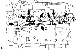
Remove the 2 bolts and disconnect the No. 5 engine wire from the fuel delivery pipe (for Direct Injection).
-
Disconnect the fuel pressure sensor connector, knock control sensor connector and 4 fuel injector set connectors.
-
Disengage the 2 clamps and remove the No. 5 engine wire.
-
-
REMOVE FUEL DELIVERY PIPE WITH SENSOR ASSEMBLY
-
REMOVE DIRECT FUEL INJECTOR ASSEMBLY
-
REMOVE FUEL INJECTOR SEAL
-
REMOVE EGR VALVE WITH COOLER ASSEMBLY
-
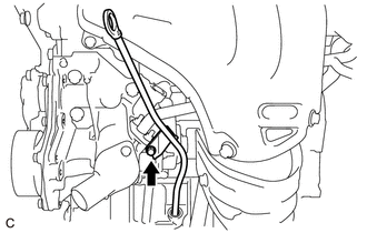
REMOVE V-RIBBED BELT TENSIONER ASSEMBLY
-
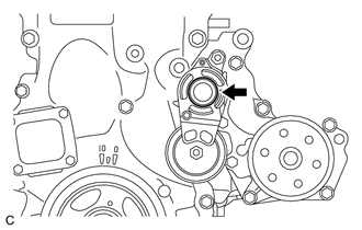
Remove the dust cover from the V-ribbed belt tensioner assembly.
-
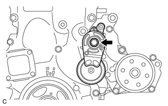
Remove the bolt and V-ribbed belt tensioner assembly from the water inlet housing.
-
-
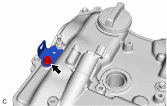
REMOVE NO. 1 WATER BY-PASS PIPE
-
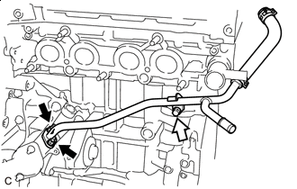
Nut Bolt Remove the bolt, 2 nuts, No. 1 water by-pass pipe and gasket.
-
-
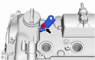
REMOVE WIRE HARNESS CLAMP BRACKET
-
Remove the bolt and wire harness clamp bracket.
-
Remove the bolt and wire harness clamp bracket.
-
-
REMOVE ENGINE WATER PUMP ASSEMBLY
-
REMOVE WATER INLET
-
REMOVE THERMOSTAT
-
REMOVE OIL COOLER ASSEMBLY
-
REMOVE ENGINE OIL TEMPERATURE SENSOR
-
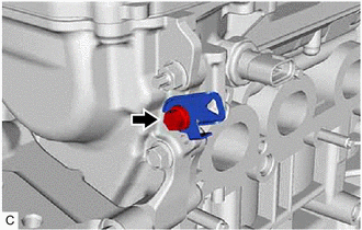
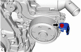
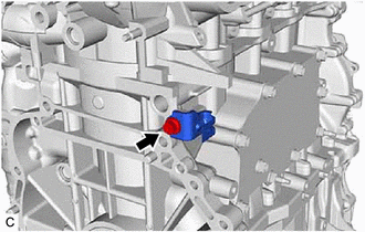
REMOVE WATER INLET HOUSING
-
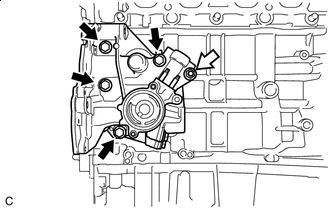
Bolt Nut Remove the 4 bolts, nut and water inlet housing from the cylinder block sub-assembly.
-
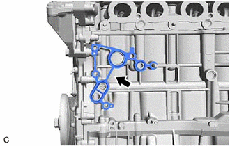
Remove the gasket from the cylinder block sub-assembly.
-
Using an E6 "TORX" socket wrench, remove the 5 stud bolts from the water inlet housing.
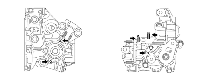
Note
If a stud bolt is deformed or its threads are damaged, replace it.
-
-
REMOVE IGNITION COIL ASSEMBLY