MONOLITHIC CONVERTER REMOVAL
PROCEDURE
-
REMOVE NO. 1 ENGINE COVER SUB-ASSEMBLY
-
REMOVE NO. 1 ENGINE UNDER COVER ASSEMBLY
-
REMOVE FRONT EXHAUST PIPE SUB-ASSEMBLY
-
Remove the 2 bolts, 2 nuts and disconnect the front exhaust pipe sub-assembly from the front No. 2 exhaust pipe sub-assembly.
-
Remove the gasket from the front exhaust pipe sub-assembly.
-
Remove the 2 bolts, 2 compression springs and front exhaust pipe sub-assembly from the exhaust manifold converter sub-assembly.
-
Remove the gasket from the exhaust manifold converter sub-assembly.
-
-
REMOVE AIR CLEANER CAP WITH AIR CLEANER HOSE
-
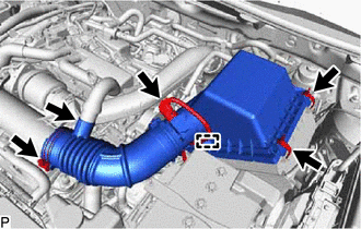
Disconnect the mass air flow meter connector.
-
Detach the wire harness clamp from the air cleaner cap sub-assembly.
-
Slide the clamp and disconnect the PCV hose from the air cleaner hose.
-
Detach the 2 clamps and remove the air cleaner cap with air cleaner hose from the air cleaner case.
-
Loosen the hose clamp and remove the air cleaner cap with air cleaner hose from the intake air connector.
-
-
REMOVE DIFFERENTIAL PRESSURE SENSOR (w/ GPF)
-
REMOVE INTAKE AIR CONNECTOR
-
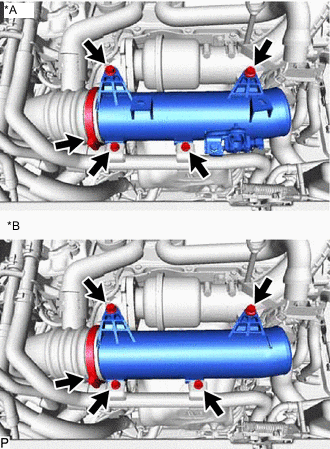
*A w/ GPF *B w/o GPF Remove the 2 bolts and disconnect the No. 1 sub-radiator hose.
-
Remove the 2 bolts.
-
Loosen the hose clamp and remove the intake air connector.
-
-
REMOVE NO. 2 AIR CLEANER HOSE
-
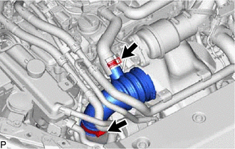
Slide the clamp and disconnect the No. 4 PCV hose from the No. 2 air cleaner hose.
-
Loosen the hose clamp and remove the No. 2 air cleaner hose.
-
-
REMOVE NO. 5 EXHAUST MANIFOLD HEAT INSULATOR
-
Remove the 4 bolts and No. 5 exhaust manifold heat insulator.
-
-
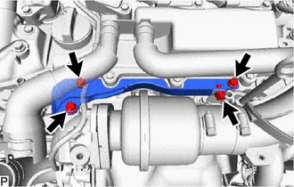
REMOVE COMPRESSOR OUTLET ELBOW
-
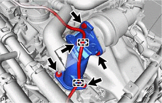
Detach the 2 clamps and disconnect the vacuum transmitting hose assembly from the compressor outlet elbow.
-
Remove the 3 bolts, 2 nus and compressor outlet elbow.
-
Remove the gasket from the compressor housing sub-assembly.
-
Remove the gasket from the intake air resonator.
-
-
REMOVE INTAKE AIR RESONATOR
-
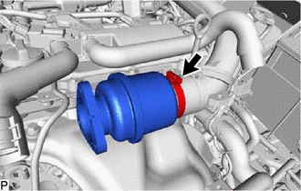
Loosen the hose clamp and remove the intake air resonator.
-
-
REMOVE AIR FUEL RATIO SENSOR
-
REMOVE NO. 1 EXHAUST MANIFOLD HEAT INSULATOR
-
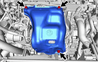
Remove the 3 bolts and No. 1 exhaust manifold heat insulator.
-
-
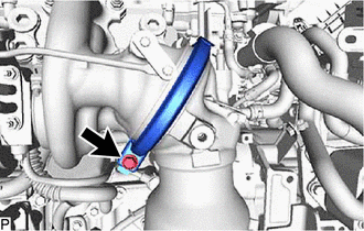
REMOVE NO. 1 PIPE (w/ GPF)
-
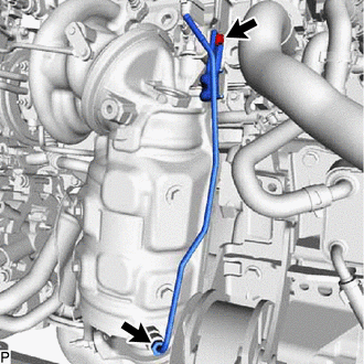
Using a 14 mm union nut wrench, disconnect the No. 1 pipe from the converter assembly.
-
Remove the bolt and No. 1 pipe.
-
-
REMOVE NO. 2 EXHAUST MANIFOLD HEAT INSULATOR
-
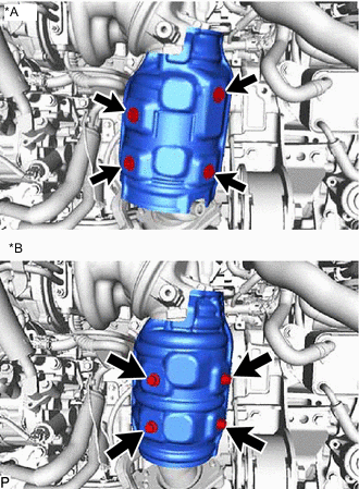
*A w/ GPF *B w/o GPF Remove the 4 bolts and No. 2 exhaust manifold heat insulator.
-
-
REMOVE EXHAUST MANIFOLD CONVERTER SUB-ASSEMBLY
-
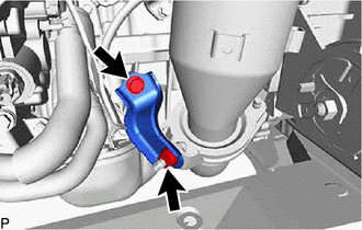
Remove the bolt, nut and manifold stay.
-
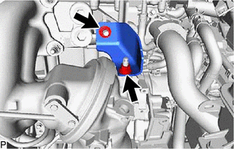
Remove the 2 nuts and turbocharger stay.
-
While pressing the exhaust manifold converter sub-assembly so it does not fall, loosen the exhaust pipe clamp, and then remove the exhaust manifold converter sub-assembly.
-
Remove the gasket.
-
-
REMOVE STUD BOLT
Note
If a stud bolt is deformed or its threads are damaged, replace it.