KEY REMINDER WARNING SYSTEM TERMINALS OF ECU
CHECK MAIN BODY ECU (INSTRUMENT PANEL JUNCTION BLOCK ASSEMBLY)
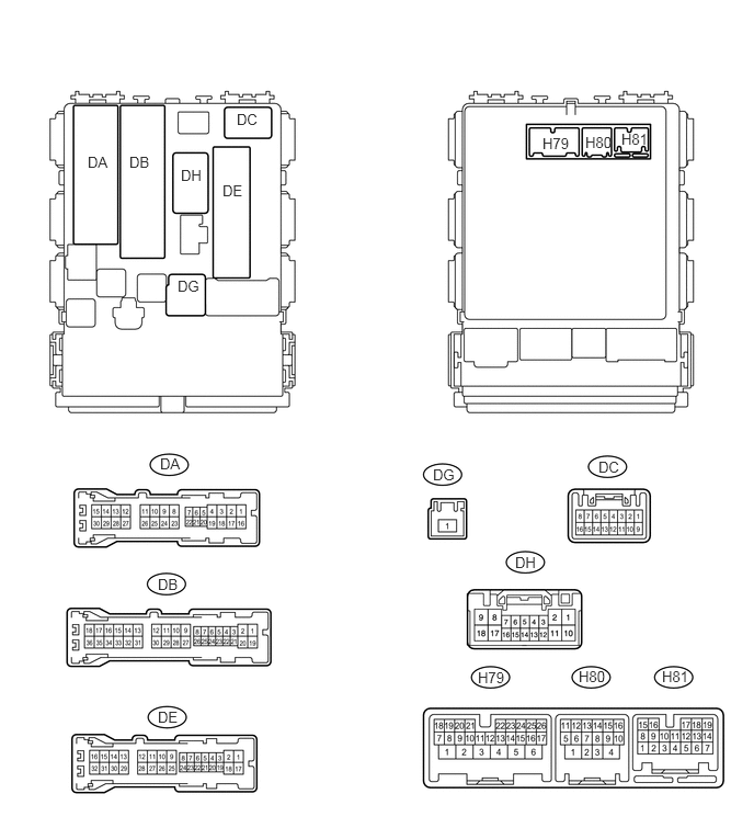
Disconnect the DB, DE, DG and H80 ECU connectors.
Measure the resistance and voltage according to the value(s) in the table below.
Terminal No. (Symbol)
Wiring Color
Terminal Description
Condition
Specified Condition
DE-28 (GND1) - Body ground
W-B - Body ground
Ground
Always
Below 1 Ω
H80-4 (GND2) - Body ground
W-B - Body ground
Ground
Always
Below 1 Ω
DB-30 (BECU) - Body ground
W - Body ground
Power source
Always
11 to 14 V
DG-1 (ALTB) - Body ground
W - Body ground
DE-23 (KSW) - Body ground
L - Body ground
Unlock warning switch signal
No key in ignition key cylinder
10 kΩ or higher
Key in ignition key cylinder
Below 1 Ω
If the result is not as specified, there may be a malfunction on the wire harness side.
Reconnect the DB, DE, DG and H80 ECU connectors.
Measure the voltage according to the value(s) in the table below.
Table 1. for LHD Terminal No. (Symbol)
Wiring Color
Terminal Description
Condition
Specified Condition
DA-21 (DCTY) - Body ground
W - Body ground
Front door courtesy light switch LH
Driver side door closed
11 to 14 V
Ignition switch off and front door courtesy light switch LH off
Below 1 V
Table 2. for RHD Terminal No. (Symbol)
Wiring Color
Terminal Description
Condition
Specified Condition
DC-6 (DCTY) - Body ground
BR - Body ground
Front door courtesy light switch RH
Driver side door closed
11 to 14 V
Ignition switch off and front door courtesy light switch RH off
Below 1 V
If the result is not as specified, the ECU may have a malfunction.