REAR SEAT ENTERTAINMENT SYSTEM Sound Signal Circuit between Multi-display Controller and Television Display
| DTC Code | DTC Name |
|---|---|
| Sound Signal Circuit between Multi-display Controller and Television Display |
DESCRIPTION
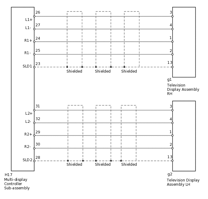
This is the sound signal circuit between the multi-display controller sub-assembly and the television display assembly RH and LH.
WIRING DIAGRAM
PROCEDURE
CHECK HARNESS AND CONNECTOR (MULTI-DISPLAY CONTROLLER - HEADPHONE TERMINAL)
Disconnect the H17 multi-display controller sub-assembly connector.
Disconnect the g1 television display assembly RH connector.
Disconnect the g2 television display assembly LH connector.
Measure the resistance according to the value(s) in the table below.
Standard Resistance
Tester Connection
Condition
Specified Condition
H17-26 (L1+) - g1-3
Always
Below 1 Ω
H17-27 (L1-) - g1-4
Always
Below 1 Ω
H17-24 (R1+) - g1-1
Always
Below 1 Ω
H17-25 (R1-) - g1-2
Always
Below 1 Ω
H17-23 (SLD1) - g1-13
Always
Below 1 Ω
H17-31 (L2+) - g2-3
Always
Below 1 Ω
H17-32 (L2-) - g2-4
Always
Below 1 Ω
H17-29 (R2+) - g2-1
Always
Below 1 Ω
H17-30 (R2-) - g2-2
Always
Below 1 Ω
H17-28 (SLD2) - g2-13
Always
Below 1 Ω
H17-26 (L1+) - Body ground
Always
10 kΩ or higher
H17-27 (L1-) - Body ground
Always
10 kΩ or higher
H17-24 (R1+) - Body ground
Always
10 kΩ or higher
H17-25 (R1-) - Body ground
Always
10 kΩ or higher
H17-23 (SLD1) - Body ground
Always
10 kΩ or higher
H17-31 (L2+) - Body ground
Always
10 kΩ or higher
H17-32 (L2-) - Body ground
Always
10 kΩ or higher
H17-29 (R2+) - Body ground
Always
10 kΩ or higher
H17-30 (R2-) - Body ground
Always
10 kΩ or higher
H17-28 (SLD2) - Body ground
Always
10 kΩ or higher
Result
Result
OK
NG
NG REPAIR OR REPLACE HARNESS OR CONNECTOR