AIR CONDITIONING SYSTEM Cooling Box Circuit
| DTC Code | DTC Name |
|---|---|
| Cooling Box Circuit |
DESCRIPTION
When the cooler control switch sub-assembly is pushed, the blower motor sub-assembly and cooler magnet valve assembly controlled by the air conditioning amplifier assembly and air conditioning amplifier assembly (for the cooling box) operate. If the cooling box assembly does not operate when the cooler control switch sub-assembly is pushed, there may be a problem in the circuit shown below.
WIRING DIAGRAM
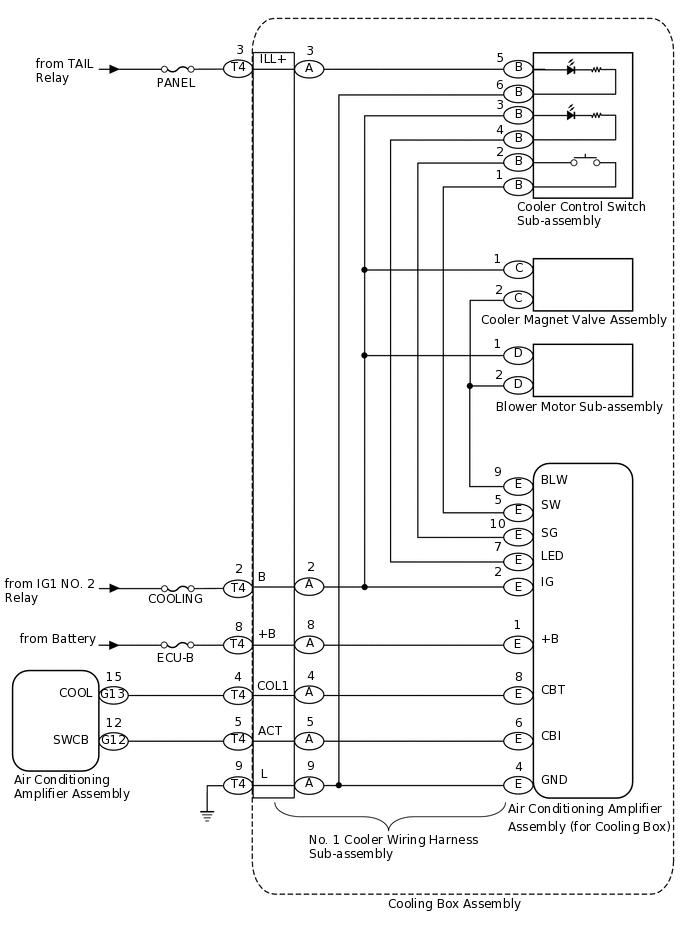
CAUTION / NOTICE / HINT
Inspect the fuses for circuits related to this system before performing the following inspection procedure.
PROCEDURE
CHECK HARNESS AND CONNECTOR (COOLING BOX - BATTERY AND BODY GROUND)
-
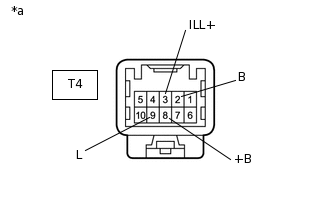
*a
Front view of wire harness connector
(to Cooling Box Assembly)
Disconnect the T4 cooling box connector.
Measure the voltage according to the value(s) in the table below.
Standard Voltage
Tester Connection
Switch Condition
Specified Condition
T4-3 (ILL+) - Body ground
Headlight dimmer switch off
Below 1 V
T4-3 (ILL+) - Body ground
Headlight dimmer switch on
11 to 14 V
T4-2 (B) - Body ground
Engine switch off
Below 1 V
T4-2 (B) - Body ground
Engine switch on (IG)
11 to 14 V
T4-8 (+B) - Body ground
Always
11 to 14 V
Measure the resistance according to the value(s) in the table below.
Standard Resistance
Tester Connection
Condition
Specified Condition
T4-9 (L) - Body ground
Always
Below 1 Ω
Result
Result
OK
NG
NG REPAIR OR REPLACE HARNESS OR CONNECTOR
-
CHECK HARNESS AND CONNECTOR (AIR CONDITIONING AMPLIFIER - COOLING BOX)
Disconnect the G13 and G12 amplifier connectors.
Disconnect the T4 cooling box connector.
Measure the resistance according to the value(s) in the table below.
Standard Resistance
Tester Connection
Condition
Specified Condition
G13-15 (COOL) - T4-4 (COL1)
Always
Below 1 Ω
G12-12 (SWCB) - T4-5 (ACT)
Always
Below 1 Ω
G13-15 (COOL) - Body ground
Always
10 kΩ or higher
G12-12 (SWCB) - Body ground
Always
10 kΩ or higher
Result
Result
OK
NG
NG REPAIR OR REPLACE HARNESS OR CONNECTOR
INSPECT COOLER CONTROL SWITCH SUB-ASSEMBLY
-
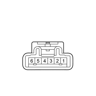
Remove the cooler control switch sub-assembly
Measure the resistance according to the value(s) in the table below.
Standard Resistance
Tester Connection
Switch Condition
Specified Condition
1 - 2
Cooler control switch sub-assembly on
Below 1 Ω
1 - 2
Cooler control switch sub-assembly off
10 kΩ or higher
Apply battery voltage to the cooler control switch sub-assembly connector and check that the cooler control switch sub-assembly illuminates.
OK
Measurement Condition
Specified Condition
Battery positive (+) → Terminal 3
Battery negative (-) → Terminal 4
LED illuminates
Battery positive (+) → Terminal 5
Battery negative (-) → Terminal 6
LED illuminates
Result
Result
OK
NG
-
INSPECT BLOWER MOTOR SUB-ASSEMBLY
-

Remove the blower motor sub-assembly
Apply battery voltage to the blower motor sub-assembly and check that the blower motor sub-assembly operates smoothly.
OK
Measurement Condition
Specified Condition
Battery positive (+) → Terminal 1
Battery negative (-) → Terminal 2
Blower motor sub-assembly operates smoothly
Result
Result
OK
NG
-
INSPECT NO. 1 COOLER WIRING HARNESS SUB-ASSEMBLY
Remove the No. 1 cooler wiring harness sub-assembly
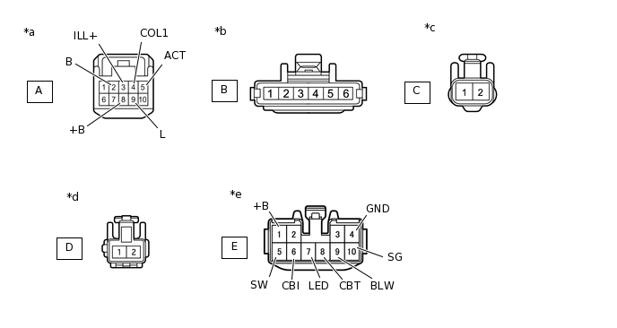
*a
Front view of wire harness connector
(to Vehicle Harness)
*b
Front view of wire harness connector
(to Cooler Control Switch Sub-assembly)
*c
Front view of wire harness connector
(to Cooler Magnet Valve Assembly)
*d
Front view of wire harness connector
(to Blower Motor Sub-assembly)
*e
Front view of wire harness connector
(to Air Conditioning Amplifier Assembly [for Cooling Box])
-
-
Measure the resistance according to the value(s) in the table below.
Standard Resistance
Tester Connection
Condition
Specified Condition
A-3 (ILL+) - B-5
Always
Below 1 Ω
A-2 (B) - E-2 (IG)
Always
Below 1 Ω
A-8 (+B) - E-1 (+B)
Always
Below 1 Ω
A-4 (COL1) - E-8 (CBT)
Always
Below 1 Ω
A-5 (ACT) - E-6 (CBI)
Always
Below 1 Ω
A-9 (L) - E-4 (GND)
Always
Below 1 Ω
A-9 (L) - B-6
Always
Below 1 Ω
A-2 (B) - B-3
Always
Below 1 Ω
B-4 - E-7 (LED)
Always
Below 1 Ω
B-2 - E-10 (SG)
Always
Below 1 Ω
B-1 - E-5 (SW)
Always
Below 1 Ω
A-2 (B) - C-1
Always
Below 1 Ω
C-2 - D-2
Always
Below 1 Ω
A-2 (B) - D-1
Always
Below 1 Ω
D-2 - E-9 (BLW)
Always
Below 1 Ω
Result
Result
OK
NG