SFI SYSTEM
-
CONSTRUCTION
-
The Magnetic Resistance Element (MRE) type crank position sensor is used. The crank angle sensor plate of the crankshaft consists of 34 teeth with 2 teeth missing. The crank position sensor detects the crankshaft rotation signals every 10°, and the missing teeth are used to determine the top dead center.
-
Magnetic Resistance Element (MRE) sensors are used for the crank position sensor and camshaft position sensors.
-
The crank angle sensor plate for the crank position sensor is installed on the crankshaft. The crank angle sensor plate has 34 teeth, with 2 teeth missing, at 10° intervals. Based on these teeth, the crank position sensor transmits crankshaft position signals (NE signal) consisting of 33 high and low output pulses every 10° per revolution of the crankshaft, and 1 high and low output pulse every 30°. The ECM uses the NE signal for detecting the crankshaft position as well as for detecting the engine speed. It uses the missing teeth signal to determine the top dead center.
-
The camshaft position sensors (intake and exhaust) use timing rotors installed on the intake and exhaust camshafts. Based on the timing rotor, the sensor outputs camshaft position signals (G2 signal) consisting of 3 (3 high output, 3 low output) pulses for every 2 revolutions of the crankshaft. The ECM compares the G2 and NE signals to detect the camshaft position and identify the cylinder.
Figure 1. Camshaft Position Sensor
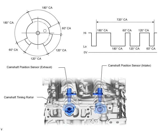
Figure 2. Crank Position Sensor
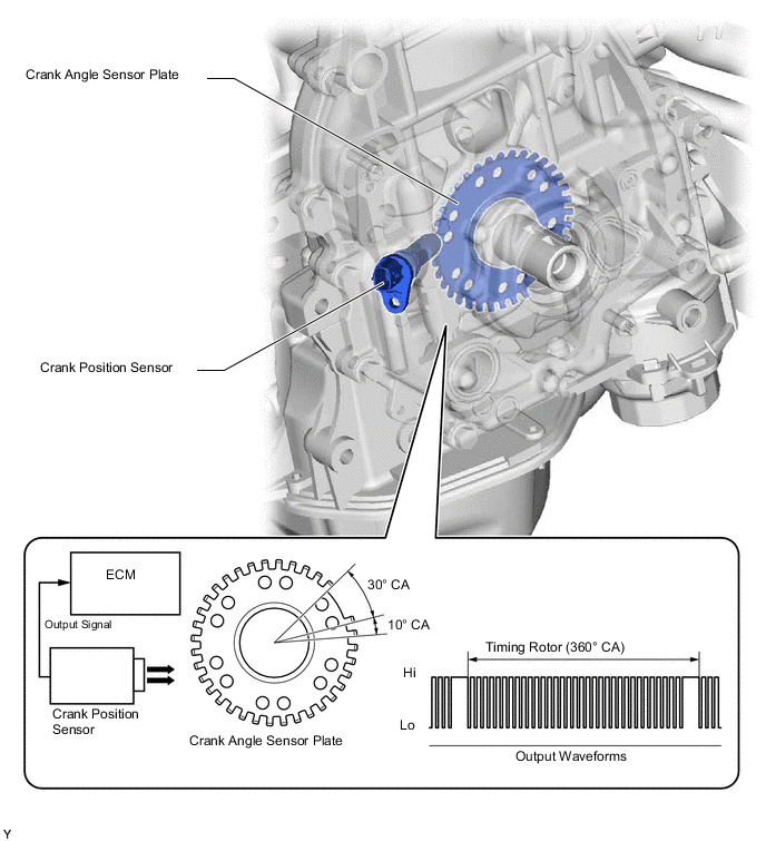
Figure 3. Sensor Output Waveforms
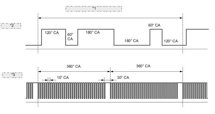
*1 Camshaft Timing Rotor (720° CA) *2 Camshaft Position Sensor *3 Crank Position Sensor -
The MRE type sensor consists of an MRE, a magnet and a sensor.
-
The direction of the magnetic field changes due to the profile (protruding and non-protruding portions) of the timing rotor or crank angle sensor plate, which passes by the sensor. As a result, the resistance of the MRE changes, and the output voltage to the ECM changes to high or low. The ECM detects the crankshaft and camshaft positions based on this output voltage.
-
The differences between the MRE type sensor and the pick-up coil type sensor used on the conventional models are as follows:
-
The MRE type sensor outputs a constant level of high and low digital signals regardless of the engine speed. Therefore, the MRE type sensor can detect the positions of the crankshaft and camshaft at an early stage of cranking.
-
The pick-up coil type sensor outputs analog signals with levels that change with the engine speed.
-
-