CONTINUOUSLY VARIABLE TRANSAXLE ASSEMBLY REMOVAL
CAUTION / NOTICE / HINT
The necessary procedures (adjustment, calibration, initialization, or registration) that must be performed after parts are removed, installed, or replaced during the continuously variable transaxle assembly removal/installation are shown below.
Necessary Procedure After Parts Removed/Installed/Replaced
Replacement Part or Procedure |
Necessary Procedures |
Effects/Inoperative when not Performed |
Link |
|---|---|---|---|
Replacement of continuously variable transaxle assembly |
|
|
PROCEDURE
PRECAUTION
CAUTION:The engine assembly with continuously variable transaxle assembly is very heavy. Be sure to follow the procedure described in the repair manual, or the engine lifter may suddenly drop.
REMOVE FLYWHEEL HOUSING UNDER COVER
-
Remove the flywheel housing under cover.
-
REMOVE DRIVE PLATE AND TORQUE CONVERTER ASSEMBLY SETTING BOLT
-
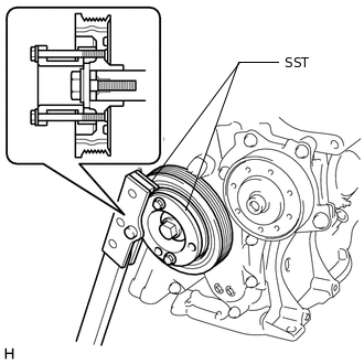
Using SST, hold the crankshaft pulley.
09213-54015
09330-00021
Tip:Part number of installation bolt for SST (crankshaft pulley holding tool): 91551-00850 (quantity: 2)
-
Remove the 6 drive plate and torque converter assembly setting bolts.
-
REMOVE ENGINE ASSEMBLY WITH TRANSAXLE
for 3ZR-FE:
for 3ZR-FAE:
DISCONNECT NO. 3 WATER BY-PASS HOSE
-
Slide the clip and disconnect the No. 3 water by-pass hose from the oil cooler.
-
DISCONNECT NO. 5 WATER BY-PASS HOSE
-
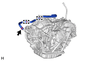
Slide the clip and disconnect the No. 5 water by-pass hose from the oil cooler.
Disconnect the No. 5 water by-pass hose from the 2 clamps.
-
DISCONNECT ENGINE WIRE
-
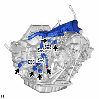
Disconnect the 5 connectors and detach the 4 clamps.
Remove the bolt and disconnect the engine wire.
-
Disconnect the 2 connectors and detach the 2 clamps.
Remove the 2 bolts and nut disconnect the engine wire.
-
DISCONNECT BREATHER PLUG HOSE
-
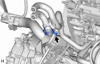
Disconnect the breather plug hose from the clamp.
-
REMOVE STARTER ASSEMBLY
for 3ZR-FE:
for 3ZR-FAE:
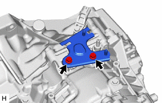
REMOVE FRONT ENGINE MOUNTING BRACKET
-
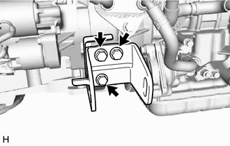
Remove the 3 bolts and front engine mounting bracket from the continuously variable transaxle assembly.
-
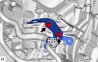
REMOVE REAR ENGINE MOUNTING BRACKET
-
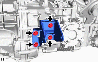
Remove the 4 bolts and rear engine mounting bracket from the continuously variable transaxle assembly.
-
REMOVE ENGINE MOUNTING BRACKET LH
-
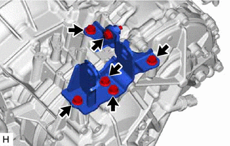
Remove the 6 bolts, engine mounting bracket LH and engine mounting stay LH from the continuously variable transaxle assembly.
-
REMOVE MANIFOLD STAY
REMOVE DRIVE SHAFT BEARING BRACKET
REMOVE TRANSFER ASSEMBLY
REMOVE CONTINUOUSLY VARIABLE TRANSAXLE ASSEMBLY
-
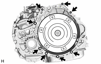
Remove the 8 bolts and continuously variable transaxle assembly from the engine assembly.
Note:To prevent damage to the 2 knock pins, do not pry between the continuously variable transaxle assembly and engine assembly.
-
REMOVE TORQUE CONVERTER ASSEMBLY
Remove the torque converter assembly from the continuously variable transaxle assembly.
Note:Remove the torque converter assembly from the input shaft horizontally.
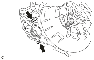
REMOVE CVT TYPE T OIL SEAL
CAUTION:Do not remove the front oil pump assembly from the continuously variable transaxle assembly main body, as there is a possibility of the entry of dust and foreign matter.
Clean the work area, the tools to be used, and other equipment, etc. thoroughly before the operation, as there is the possibility that a continuously variable transaxle assembly malfunction, which may prevent the vehicle from being driven, may occur if dust or fine foreign matter enters the continuously variable transaxle assembly.
Do not use cotton work gloves, cloths, paper towels, etc. that may produce lint, dust or foreign matter.
Perform the operation as quickly as possible, as dust and foreign matter may enter the continuously variable transaxle assembly while the torque converter assembly is not attached to it.
Do not use an air gun until the torque converter assembly has been installed, as it may cause dust and foreign matter to be stirred up.
Clean the tips of both the claws of SST and the center bolt.
09308-10010
-
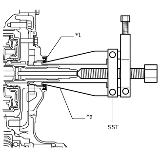
*1
CVT Type T Oil Seal
*a
Claw
Using SST, remove the CVT type T oil seal from the continuously variable transaxle assembly.
Note:Pay attention to the angle of the claws of SST when opening them, and ensure that they do not come into contact with the oil pump housing, as there is the possibility that metal particles may be produced if they do.
REMOVE NO. 1 TRANSMISSION CONTROL CABLE BRACKET
-
Disconnect the clamp from the No. 1 transmission control cable bracket.
Remove the 2 bolts and No. 1 transmission control cable bracket from the continuously variable transaxle assembly.
-
REMOVE TRANSMISSION CONTROL CABLE SUPPORT
-
Remove the 2 bolts and transmission control cable support from the continuously variable transaxle assembly.
-
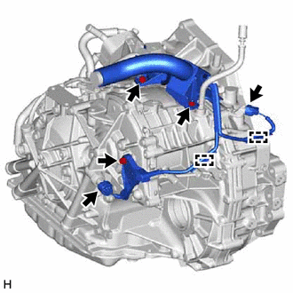
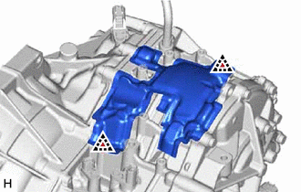
REMOVE WIRE HARNESS CLAMP BRACKET
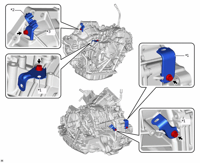
*1
Wire Harness Clamp Bracket
*2
Water By-pass Hose Clamp
*3
Water Hose Clamp Bracket
-
-
Remove the bolt and water hose clamp bracket from the continuously variable transaxle assembly.
Remove the water by-pass hose clamp from the water hose clamp bracket.
Remove the 3 bolts and 3 wire harness clamp brackets from the continuously variable transaxle assembly.
REMOVE OIL COOLER TUBE UNION
-
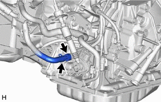
Slide the clip and disconnect the No. 1 transmission oil cooler hose from the oil cooler tube union.
Note:Do not damage the coating of the hose insertion part of the oil cooler tube union.
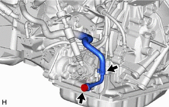
Remove the oil cooler tube union from the continuously variable transaxle assembly.
Remove the O-ring from the oil cooler tube union.
-
REMOVE OIL COOLER ELBOW SUB-ASSEMBLY
-
Slide the clip and disconnect the No. 2 transmission oil cooler hose from the oil cooler elbow sub-assembly.
Note:Do not damage the coating of the hose insertion part of the oil cooler elbow sub-assembly.
Remove the union bolt, oil cooler elbow sub-assembly and gasket from the continuously variable transaxle assembly.
-
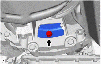
REMOVE TRANSMISSION OIL FILLER TUBE STRAIGHT SCREW PLUG
Tip:Perform this procedure only when replacement of the transmission oil filler tube straight screw plug is necessary.
-
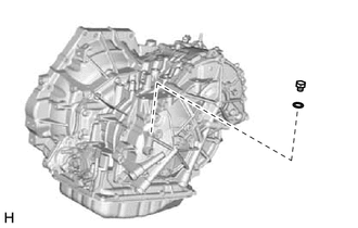
Remove the transmission oil filler tube straight screw plug and gasket from the continuously variable transaxle assembly.
-
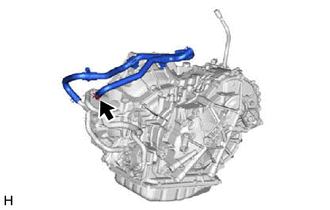
REMOVE BREATHER PLUG HOSE
Tip:Perform this procedure only when replacement of the breather plug hose is necessary.
Note:When replacing the continuously variable transaxle assembly, be sure to install the breather plug hose.
-
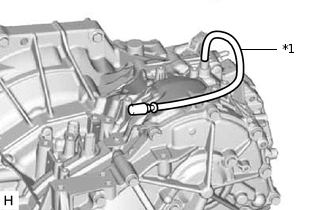
*1
Breather Plug Hose
Remove the breather plug hose from the continuously variable transaxle assembly.
-
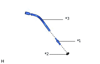
*1
Breather Plug
*2
O-ring
*3
Breather Plug Hose
Remove the breather plug from the breather plug hose.
Remove the O-ring from the breather plug.
-
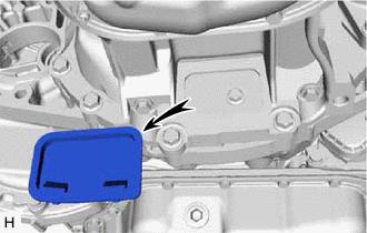
REMOVE AUTOMATIC TRANSMISSION CASE COVER
-
Remove the 2 clips and automatic transmission case cover from the continuously variable transaxle assembly.
-
REMOVE TRANSFER AND TRANSAXLE SETTING STUD BOLT
Transfer side
-
Remove the 2 transfer and transaxle setting stud bolts.
-
INSPECT TORQUE CONVERTER ASSEMBLY
INSPECT DRIVE PLATE AND RING GEAR SUB-ASSEMBLY