СИСТЕМА SFI, Diagnostic DTC:P2A00, P2A03
| DTC Code | DTC Name |
|---|---|
| P2A00 | A/F Sensor Circuit Slow Response (Bank 1 Sensor 1) |
| P2A03 | A/F Sensor Circuit Slow Response (Bank 2 Sensor 1) |
DESCRIPTION
Refer to DTC P2195 Click here.
| DTC No. | DTC Detection Condition | Trouble Area |
|---|---|---|
| P2A00 P2A03 |
Calculated test value for A/F sensor response rate deterioration level is less threshold |
|
WIRING DIAGRAM
Refer to DTC P2195 Click here.
INSPECTION PROCEDURE
Tech Tips
Intelligent tester only:
Malfunctioning areas can found by performing the Active Test / Control the Injection volume for A/F sensor operation. The "Control the injection volume for A/F sensor" operation can determine if the A/F sensor, heated oxygen sensor or other potential trouble areas are malfunctioning or not.
Perform Active Test using the intelligent tester.
Tech Tips
"Control the injection volume for A/F sensor" is an Active Test which changes the injection volume to -12.5% or +25%.
-
Connect the intelligent tester to the DLC3.
-
Start the engine and turn the tester ON.
-
Warm up the engine by running the engine at 2,500 rpm for approximately 90 seconds.
-
Enter the following menus: Powertrain / Engine and ECT / Active Test / Control the injection volume for A/F sensor.
-
Enter the following monitor items: AFS B1S1 and O2S B1S2 or AFS B2S1 and O2S B2S2.
-
Perform the "Control the injection volume for A/F sensor" operation with the engine in a idling condition (press the right or left button).
Tech Tips
-
The "Control the injection volume for A/F sensor" operation lowers the fuel injection volume by 12.5 % or increases the injection volume by 25 %.
-
Each sensor reacts in accordance with increases and decreases in the fuel injection volume.
| Tester Display (Sensor) |
Injection Volume | Status | Voltage |
|---|---|---|---|
| AFS B1S1 or AFS B2S1 (A/F) |
+25 % | Rich | Less than 3.0 |
| AFS B1S1 or AFS B2S1 (A/F) |
-12.5 % | Lean | More than 3.35 |
| O2S B1S2 or O2S B2S2 (heated oxygen sensor) |
+25 % | Rich | More than 0.55 |
| O2S B1S2 or O2S B2S2 (heated oxygen sensor) |
-12.5 % | Lean | Less than 0.4 |
Note
The A/F sensor has an output delay of a few seconds and the heated oxygen sensor has a maximum output delay of approximately 20 seconds.
| Case | A/F Sensor (Sensor 1) Output Voltage |
Heated Oxygen Sensor (Sensor 2) Output Voltage |
Main Suspected Trouble Areas | ||
|---|---|---|---|---|---|
| 1 | Injection volume +25 % -12.5 % |
 |
Injection volume +25 % -12.5 % |
|
- |
| Output voltage More than 3.35 V Less than 3.0 V |
 |
Output voltage More than 0.55 V Less than 0.4 V |
 |
||
| 2 | Injection volume +25 % -12.5 % |
|
Injection volume +25 % -12.5 % |
|
|
| Output voltage Almost no reaction |
 |
Output voltage More than 0.55 V Less than 0.4 V |
|
||
| 3 | Injection volume +25 % -12.5 % |
|
Injection volume +25 % -12.5 % |
|
|
| Output voltage More than 3.35 V Less than 3.0 V |
|
Output voltage Almost no reaction |
|
||
| 4 | Injection volume +25 % -12.5 % |
|
Injection volume +25 % -12.5 % |
|
|
| Output voltage Almost no reaction |
|
Output voltage Almost no reaction |
|
||
-
Following the A/F CONTROL procedure enables technicians to check and graph the voltage outputs of both the A/F and heated oxygen sensors.
-
Enter the following menus on the tester: Powertrain / Engine and ECT / Active Test / Control the injection volume for A/F sensor and Data List / AFS B1S1 and O2S B1S2 or AFS B2S1 and O2S B2S2.
Tech Tips
-
Read freeze frame data using the intelligent tester. Freeze frame data records the engine conditions when a malfunction is detected. When troubleshooting, freeze frame data can help determine if the vehicle was running or stopped, if the engine was warmed up or not, if the air-fuel ratio was lean or rich, and other data from the time the malfunction occurred.
-
These DTCs are related to the A/F sensor.
-
These DTCs are recorded when A/F sensor has malfunction, although the caption is oxygen sensor.
PROCEDURE
-
CHECK OTHER DTC OUTPUT (BESIDES A/F SENSOR DTC)
-
Connect the intelligent tester to the DLC3.
-
Turn the ignition switch ON and turn the tester ON.
-
Enter the following menus: Powertrain / Engine and ECT / DTC.
-
Read DTCs.
Result Display Proceed to DTC P2A00 and/or P2A03 are output A DTC P2A00 and/or P2A03 and other codes are output B Tech Tips
If any other code besides P2A00 and/or P2A03 are output, perform troubleshooting for those DTCs first.
B 
GO TO RELEVANT DTC CHART
A 
-
-
INSPECT AIR FUEL RATIO SENSOR (HEATER RESISTANCE)
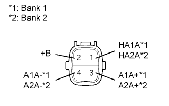
-
Disconnect the A/F sensor connector.
-
Measure the resistance of the A/F sensor.
Standard resistance (Bank 1 Sensor 1) Tester Connection Condition Specified Condition 1 (HA1A) - 2 (+B) 20°C (68°F) 1.8 to 3.4 Ω 1 (HA1A) - 4 (A1A-) - 10 kΩ or higher Standard resistance (Bank 2 Sensor 1) Tester Connection Condition Specified Condition 1 (HA2A) - 2 (+B) 20°C (68°F) 1.8 to 3.4 Ω 1 (HA2A) - 4 (A2A-) - 10 kΩ or higher
NG
REPLACE AIR FUEL RATIO SENSOR
OK
-
-
CHECK WIRE HARNESS (A/F SENSOR -ECM)
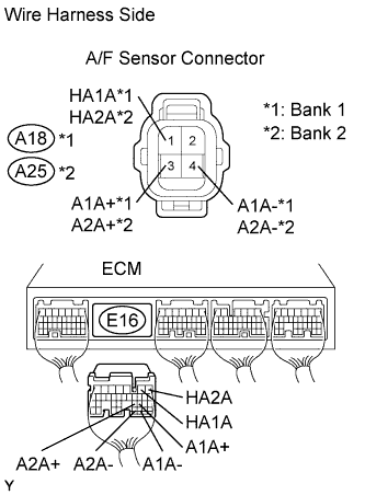
-
Disconnect the A18 or A25 A/F sensor connector.
-
Disconnect the E6 ECM connector.
-
Measure the resistance of the wire harness side connectors.
Standard resistance (Bank 1 Sensor 1) Tester Connection Specified Condition A18-1 (HA1A) - E16-2 (HA1A) Below 1 Ω A18-3 (A1A+) - E16-22 (A1A+) Below 1 Ω A18-4 (A1A-) - E16-30 (A1A-) Below 1 Ω A18-1 (HA1A) or E16-2 (HA1A) - Body ground 10 kΩ or higher A18-3 (A1A+) or E16-22 (A1A+) - Body ground 10 kΩ or higher A18-4 (A1A-) or E16-30 (A1A-) - Body ground 10 kΩ or higher Standard resistance (Bank 2 Sensor 1) Tester Connection Specified Condition A25-1 (HA2A) - E16-1 (HA2A) Below 1 Ω A25-3 (A2A+) - E16-23 (A2A+) Below 1 Ω A25-4 (A2A-) - E16-31 (A2A-) Below 1 Ω A25-1 (HA2A) or E16-1 (HA2A) - Body ground 10 kΩ or higher A25-3 (A2A+) or E16-23 (A2A+) - Body ground 10 kΩ or higher A25-4 (A2A-) or E16-31 (A2A-) - Body ground 10 kΩ or higher 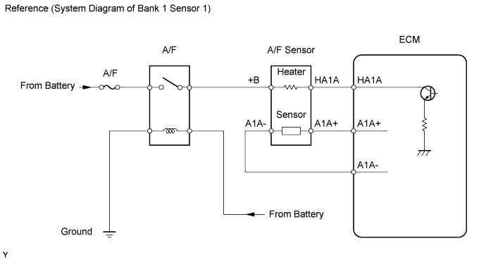
NG
REPAIR OR REPLACE HARNESS AND CONNECTOR
OK
-
-
PERFORM CONFIRMATION DRIVING PATTERN
NEXT
-
CHECK WHETHER OUTPUT DTC RECURS (P2A00 OR P2A03)
-
Connect the intelligent tester to the DLC3.
-
Turn the ignition switch ON and turn the tester ON.
-
Enter the following menus: Powertrain / Engine and ECT / DTC.
-
Read DTCs.
Result Display Proceed to DTC P2A00 and/or P2A03 are not output A DTC P2A00 and/or P2A03 are output B
B
CHECK FOR INTERMITTENT PROBLEMS
A
-
-
REPLACE AIR FUEL RATIO SENSOR
NEXT
-
PERFORM CONFIRMATION DRIVING PATTERN
NEXT
-
CHECK WHETHER DTC OUTPUT RECURS (P2A00 OR P2A03)
-
Connect the intelligent tester to the DLC3.
-
Turn the ignition switch ON and turn the tester ON.
-
Enter the following menus: Powertrain / Engine and ECT / DTC.
-
Read DTCs.
Result Display Proceed to DTC P2A00 and/or P2A03 are not output A DTC P2A00 and/or P2A03 are output B
A
CHECK AIR FUEL RATIO EXTREMELY LEAN OR RICH
B 
END
-