MAIN BODY ECU INSTALLATION
PROCEDURE
-
INSTALL NETWORK GATEWAY ECU
Note
-
Prevent foreign matter from being mixed into the engagement, connector or terminals.
-
Do not touch the network gateway ECU connector terminals.
Tech Tips
-
Use the same procedure for RHD and LHD vehicles.
-
The procedure listed below is for LHD vehicles.
-
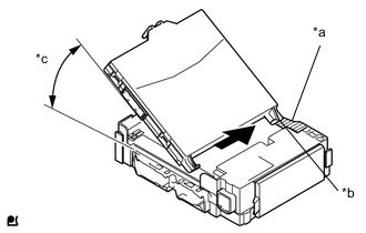
Text in Illustration *a Housing Side Wall *b Guide *c 20° or more Make the network gateway ECU guide to contact the housing side wall.
Tech Tips
The angle between the junction block and the network gateway ECU guide should be 20° or more.
-
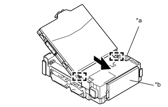
Text in Illustration *a Hosing Side Wall *b Fuse Area While aligning the guide with the housing side wall, slide the network gateway ECU toward the fuse area of the instrument panel junction block assembly and engage the 2 guides.
-
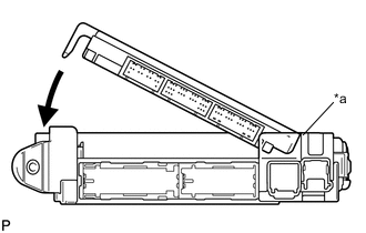
Text in Illustration *a A surface Slide the network gateway ECU until it contacts the A surface.
-
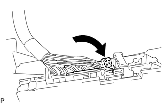
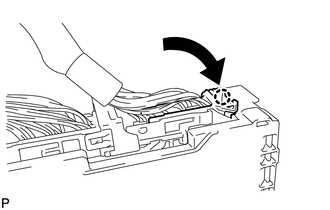
Rotate the network gateway ECU while holding it against the instrument panel junction block assembly surface (axis of rotation).
Note
-
Slide gently the network gateway ECU.
-
Do not apply strong impact to the side of the network gateway ECU.
-
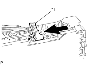
-
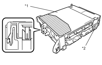
Text in Illustration *1 Network Gateway ECU *2 Instrument Panel Junction Block Assembly 
Push Area Rotate the network gateway ECU until it engages with the lock to install it.
Note
-
When pressing the network gateway ECU, press the push area as shown in the illustration.
-
A lock sound will be heard when the network gateway ECU is engaged.
-
Do not hit or weight the network gateway ECU when it engages with the instrument panel junction block assembly.
Tech Tips
If a lock sound is not heard, visually check the lock engagement. Check that the height of the network gateway ECU and instrument panel junction block assembly match.
-
-
-
INSTALL INSTRUMENT PANEL JUNCTION BLOCK ASSEMBLY
-
Connect the connector as shown in the illustration.
-
Text in Illustration *1 Lever Slide the lever as indicated by the arrow shown in the illustration.
-
Connect the connector indicated as shown in the illustration.
-
Install the instrument panel junction block assembly with the bolt and the nut.
- Torque:
- 7.5 N*m { 76 kgf*cm, 66 in.*lbf }
-
Connect 6 connectors to the instrument panel junction block assembly.
-
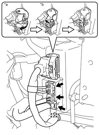
Connect the 3 connectors to the power steering ECU assembly.
-
Connect the connector to the power steering ECU assembly.
-
As shown in the illustration, return the lock lever to its original position to connect the connector and securely push in the lock of the lock lever.
Text in Illustration *a Return the lock lever *b Push the lock
-
-
-
INSTALL NO. 1 INSTRUMENT PANEL UNDER COVER SUB-ASSEMBLY (w/o Knee Airbag)
-
INSTALL NO. 1 INSTRUMENT PANEL UNDER COVER SUB-ASSEMBLY (w/ Knee Airbag)
-
INSTALL INSTRUMENT SIDE PANEL LH