CONTINUOUSLY VARIABLE TRANSAXLE SYSTEM Shift Paddle Switch Circuit
| DTC Code | DTC Name |
|---|---|
| Shift Paddle Switch Circuit |
DESCRIPTION
When the shift lever is in M, the shift range can be changed using the shift paddle switches. It is also possible to select the shift range when the vehicle is being driven with the shift lever in D by operating the shift paddle switches.
WIRING DIAGRAM
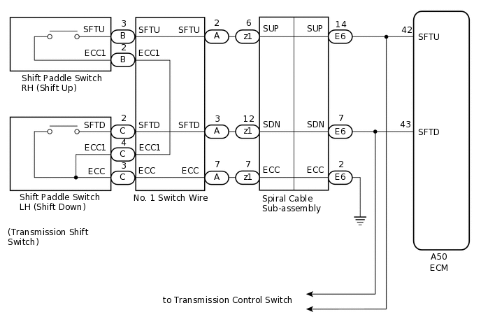
PROCEDURE
READ VALUE USING GTS (SPORTS SHIFT UP SWITCH AND SPORTS SHIFT DOWN SWITCH)
Connect the GTS to the DLC3.
Turn the ignition switch to ON.
Turn the GTS on.
Enter the following menus: Powertrain / Engine and ECT / Data List / Primary.
In accordance with the display on the GTS, read the Data List.
Powertrain > Engine and ECT > Data List
Tester Display
Measurement Item
Range
Normal Condition
Diagnostic Note
Sports Shift Up SW
Sport shift up switch status
OFF or ON
ON: Shift lever held in "+" or "+" shift paddle switch pulled
OFF: Shift lever not held in "+" or "+" shift paddle switch released
-
Sports Shift Down SW
Sport shift down switch status
OFF or ON
ON: Shift lever held in "-" or "-" shift paddle switch pulled
OFF: Shift lever not held in "-" or "-" shift paddle switch released
-
Result
Result
Proceed to
Data display is within Normal Condition range
A
Data display is not within Normal Condition range
B
INSPECT TRANSMISSION SHIFT SWITCH ASSEMBLY (SHIFT PADDLE SWITCH)
Disconnect the A50 ECM connector.
Measure the resistance according to the value(s) in the table below.
Standard Resistance
Tester Connection
Condition
Specified Condition
A50-42 (SFTU) - Body ground
"+" continuously pulled
Below 3 Ω
A50-42 (SFTU) - Body ground
Released
10 kΩ or higher
A50-43 (SFTD) - Body ground
"-" continuously pulled
Below 3 Ω
A50-43 (SFTD) - Body ground
Released
10 kΩ or higher
Connect the A50 ECM connector.
Result
Proceed to
OK
NG
CHECK HARNESS AND CONNECTOR (SPIRAL CABLE SUB-ASSEMBLY - BODY GROUND)
Disconnect the negative (-) terminal cable from the battery.
Wait for at least 90 seconds.
Remove the steering wheel assembly.
Remove the steering column cover.
Disconnect the E6 spiral cable sub-assembly connector.
Measure the resistance according to the value(s) in the table below.
Standard Resistance
Tester Connection
Condition
Specified Condition
E6-2 (ECC) - Body ground
Always
Below 1 Ω
Result
Proceed to
OK
NG
NG REPAIR OR REPLACE HARNESS OR CONNECTOR (SPIRAL CABLE SUB-ASSEMBLY - BODY GROUND)
CHECK HARNESS AND CONNECTOR (SPIRAL CABLE SUB-ASSEMBLY - ECM)
Disconnect the A50 ECM connector.
Measure the resistance according to the value(s) in the table below.
Standard Resistance
Tester Connection
Condition
Specified Condition
A50-43 (SFTD) - E6-7 (SDN)
Always
Below 1 Ω
A50-43 (SFTD) or E6-7 (SDN) - Body ground
Always
10 kΩ or higher
A50-42 (SFTU) - E6-14 (SUP)
Always
Below 1 Ω
A50-42 (SFTU) or E6-14 (SUP) - Body ground
Always
10 kΩ or higher
Connect the A50 ECM connector.
Connect the E6 spiral cable sub-assembly connector.
Result
Proceed to
OK
NG
NG REPAIR OR REPLACE HARNESS OR CONNECTOR (SPIRAL CABLE SUB-ASSEMBLY - ECM)
CHECK WIRE HARNESS AND CONNECTORS (SPIRAL CABLE SUB-ASSEMBLY - SHIFT PADDLE SWITCH)
-
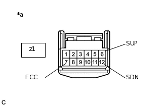
*a
Front view of wire harness connector
(to Spiral Cable Sub-assembly)
Disconnect the z1 steering pad switch connector from the spiral cable sub-assembly.
Measure the resistance according to the value(s) in the table below.
Standard Resistance
Tester Connection
Condition
Specified Condition
z1-6 (SUP) - z1-7 (ECC)
"+" continuously pulled
Below 3 Ω
z1-6 (SUP) - z1-7 (ECC)
Released
10 kΩ or higher
z1-12 (SDN) - z1-7 (ECC)
"-" continuously pulled
Below 3 Ω
z1-12 (SDN) - z1-7 (ECC)
Released
10 kΩ or higher
Result
Proceed to
OK
NG
NG INSPECT TRANSMISSION SHIFT SWITCH ASSEMBLY (SHIFT PADDLE SWITCH)Click here
-
INSPECT SPIRAL CABLE SUB-ASSEMBLY
Disconnect the z1 and E6 connectors from the spiral cable sub-assembly.
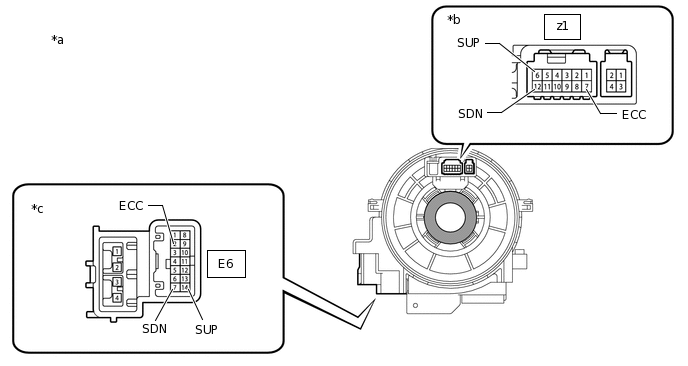
*a
Component without harness connected
(Spiral Cable Sub-assembly)
*b
Steering Pad Switch Side
*c
Vehicle Side
-
-
Measure the resistance according to the value(s) in the table below.
Standard Resistance
Tester Connection
Condition
Specified Condition
z1-7 (ECC) - E6-2 (ECC)
Always
Below 3 Ω
z1-6 (SUP) - E6-14 (SUP)
Always
Below 3 Ω
z1-12 (SDN) - E6-7 (SDN)
Always
Below 3 Ω
z1-7 (ECC) or E6-2 (ECC) - Body ground and other terminals
Always
10 kΩ or higher
z1-6 (SUP) or E6-14 (SUP) - Body ground and other terminals
Always
10 kΩ or higher
z1-12 (SDN) or E6-7 (SDN) - Body ground and other terminals
Always
10 kΩ or higher
Result
Proceed to
OK
NG
REPLACE ECM
Replace the ECM.
Result
Proceed to
NEXT
PERFORM INITIALIZATION
Note:Performing Reset Memory will clear the learned value of the yaw rate and acceleration sensor (deceleration sensor zero point calibration) and the CVT oil pressure (CVT oil pressure calibration). Make sure to perform Reset Memory, yaw rate and acceleration sensor zero point calibration, and CVT oil pressure calibration when replacing any of the parts shown in the following table:
Replaced Part
Continuously variable transaxle assembly
ECM
Oil pressure sensor
Airbag sensor assembly (Yaw rate and acceleration sensor)
After performing Reset Memory, always perform yaw rate and acceleration sensor (deceleration sensor zero point) calibration first, and then CVT oil pressure calibration.
Always perform calibration with the vehicle on level ground.
Do not shake or vibrate the vehicle during calibration.
Using the GTS, perform Reset Memory, deceleration sensor zero point calibration and CVT oil pressure calibration.
Check for DTCs again.
Result
Proceed to
NEXT
NEXT END
INSPECT TRANSMISSION SHIFT SWITCH ASSEMBLY (SHIFT PADDLE SWITCH)
-
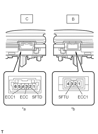
*a
Component without harness connected
(Shift paddle switch LH)
*b
Component without harness connected
(Shift paddle switch RH)
Disconnect the C and B connectors from the transmission shift switch LH and RH.
Measure the resistance according to the value(s) in the table below.
Standard Resistance (Transmission Shift Switch LH)
Tester Connection
Condition
Specified Condition
C-3 (ECC) - C-2 (SFTD)
"-" continuously pulled
Below 3 Ω
C-3 (ECC) - C-2 (SFTD)
Released
10 kΩ or higher
C-4 (ECC1) - C-2 (SFTD)
"-" continuously pulled
Below 3 Ω
C-4 (ECC1) - C-2 (SFTD)
Released
10 kΩ or higher
Standard Resistance (Transmission Shift Switch RH)
Tester Connection
Condition
Specified Condition
B-3 (SFTU) - B-2 (ECC1)
"+" continuously pulled
Below 3 Ω
B-3 (SFTU) - B-2 (ECC1)
Released
10 kΩ or higher
Result
Proceed to
OK
NG
-
INSPECT NO. 1 SWITCH WIRE
-
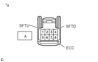
*a
Front view of wire harness connector
(to Steering Pad Switch Connector)
Connect the C and B transmission shift switch LH and RH connectors.
Disconnect the A No.1 switch wire from steering pad switch connector.
Measure the resistance according to the value(s) in the table below.
Standard Resistance
Tester Connection
Condition
Specified Condition
A-2 (SFTU) - A-7 (ECC)
"+" continuously pulled
Below 3 Ω
A-2 (SFTU) - A-7 (ECC)
Released
10 kΩ or higher
A-3 (SFTD) - A-7 (ECC)
"-" continuously pulled
Below 3 Ω
A-3 (SFTD) - A-7 (ECC)
Released
10 kΩ or higher
Result
Proceed to
OK
NG
OK REPAIR OR REPLACE HARNESS OR CONNECTOR (NO. 1 SWITCH WIRE - SPIRAL CABLE SUB-ASSEMBLY)
-