ENTRY AND START SYSTEM(for Entry Function) Back Door Entry Unlock Function does not Operate
| DTC Code | DTC Name |
|---|---|
| Back Door Entry Unlock Function does not Operate |
DESCRIPTION
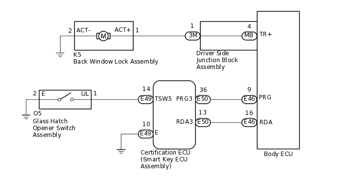
If the entry unlock function does not operate for the back door only, but the entry lock function operates, the request code is being transmitted properly from the back door. In this case, there may be a problem related to the open switch (connection between the glass hatch opener switch assembly and certification ECU (smart key ECU assembly)).
WIRING DIAGRAM
CAUTION / NOTICE / HINT
The entry and start system (for Entry Function) uses the LIN communication system and CAN communication system. Inspect the communication function by following How to Proceed with Troubleshooting. Troubleshoot the entry and start system (for Entry Function) after confirming that the communication systems are functioning properly.
When using the GTS with the engine switch off, connect the GTS to the DLC3 and turn a courtesy light switch on and off at intervals of 1.5 seconds or less until communication between the GTS and the vehicle begins. Then select Model Code "KEY REGIST" under manual mode and enter the following menus: Body Electrical / Entry&Start(CAN). While using the GTS, periodically turn a courtesy light switch on and off at intervals of 1.5 seconds or less to maintain communication between the GTS and the vehicle.
Check that there are no electrical key transmitter sub-assemblies in the vehicle.
Before performing the inspection, check that DTC B1242 (wireless door lock control) or B27B0 is not output.
Before replacing the certification ECU (smart key ECU assembly), refer to entry and start system (for Entry Function) Precaution.
After repair, confirm that no DTCs are output by performing "DTC Output Confirmation Operation".
PROCEDURE
CHECK POWER DOOR LOCK CONTROL SYSTEM
When the door control switch is operated, check that the doors unlock and lock according to the switch operation.
OK
Door locks operate normally.
Result
Proceed to
OK
NG
NG INSPECT BACK WINDOW LOCK ASSEMBLYClick here
READ VALUE USING GTS (TR/B-DOOR UNLOCK SW)
Connect the GTS to the DLC3.
Turn the engine switch on (IG).
Turn the GTS on.
Enter the following menus: Body Electrical / Entry&Start / Data List.
Read the Data List according to the display on the GTS.
Body Electrical > Entry&Start > Data List
Tester Display
Measurement Item
Range
Normal Condition
Diagnostic Note
Tr/B-Door Unlock SW
Glass hatch opener switch assembly
ON or OFF
ON: Glass hatch opener switch assembly pushed
OFF: Glass hatch opener switch assembly not pushed
Displays whether the glass hatch opener switch assembly is on or off.
Use this Data List item to help determine if there is a switch malfunction when the back door open function does not operate.
Body Electrical > Entry&Start > Data List
Tester Display
Tr/B-Door Unlock SW
OK
The GTS display changes correctly in response to the operation of the glass hatch opener switch assembly.
Result
Result
Proceed to
NG
A
OK
B
B CHECK ENTRY BACK DOOR OPEN OPERATIONClick here
CHECK HARNESS AND CONNECTOR (CERTIFICATION ECU (SMART KEY ECU ASSEMBLY) - GLASS HATCH OPENER SWITCH ASSEMBLY)
Disconnect the E49 certification ECU (smart key ECU assembly) connector.
Disconnect the O5 glass hatch opener switch assembly connector.
Measure the resistance according to the value(s) in the table below.
Standard Resistance
Tester Connection
Condition
Specified Condition
E49-14 (TSW5) - O5-1 (UL)
Always
Below 1 Ω
O5-2 (E) - Body ground
Always
Below 1 Ω
E49-14 (TSW5) or O5-1 (UL) - Body ground
Always
10 kΩ or higher
Result
Proceed to
OK
NG
NG REPAIR OR REPLACE HARNESS OR CONNECTOR
INSPECT GLASS HATCH OPENER SWITCH ASSEMBLY
Remove the glass hatch opener switch assembly.
Inspect the glass hatch opener switch assembly.
Result
Proceed to
OK
NG
CHECK ENTRY BACK DOOR OPEN OPERATION
Reconnect all connectors.
Check the entry back door open function.
OK
Entry back door open function operates normally.
Result
Proceed to
OK
NG
OK END (CONNECTOR WAS NOT CONNECTED SECURELY)
REPLACE BODY ECU
Replace the body ECU with a new or known good one.
Result
Proceed to
NEXT
CHECK ENTRY BACK DOOR OPEN OPERATION
Check the entry back door open function.
OK
Entry back door open function operates normally.
Result
Proceed to
OK
NG
OK END (BODY ECU WAS DEFECTIVE)
NG REPLACE CERTIFICATION ECU (SMART KEY ECU ASSEMBLY)
INSPECT BACK WINDOW LOCK ASSEMBLY
Remove the back window lock assembly.
Inspect the back window lock assembly.
Result
Proceed to
OK
NG
CHECK HARNESS AND CONNECTOR (BACK WINDOW LOCK ASSEMBLY - DRIVER SIDE JUNCTION BLOCK ASSEMBLY)
Disconnect the K5 back window lock assembly connector.
Disconnect the 3M driver side junction block assembly connector.
Measure the resistance according to the value(s) in the table below.
Standard Resistance
Tester Connection
Condition
Specified Condition
K5-1 (ACT+) - 3M-1 (TR+)
Always
Below 1 Ω
K5-2 (ACT-) - Body ground
Always
Below 1 Ω
K5-1 (ACT+) or 3M-1 (TR+) - Body ground
Always
10 kΩ or higher
Result
Proceed to
OK
NG
NG REPAIR OR REPLACE HARNESS OR CONNECTOR
INSPECT DRIVER SIDE JUNCTION BLOCK ASSEMBLY
Remove the driver side junction block assembly.
Measure the resistance according to the value(s) in the table below.
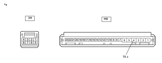
*a
Component without harness connected
(Driver Side Junction Block Assembly)
-
-
Standard Resistance
Tester Connection
Condition
Specified Condition
3M-1 - MB-4 (TR+)
Always
Below 1 Ω
Result
Proceed to
OK
NG