SFI SYSTEM, Diagnostic DTC:P0139
| DTC Code | DTC Name |
|---|---|
| P0139 | Oxygen Sensor Circuit Slow Response (Bank 1 Sensor 2) |
DESCRIPTION
Refer to DTC P0137.
DTC No. |
Detection Item |
DTC Detection Condition |
Trouble Area |
MIL |
Memory |
|---|---|---|---|---|---|
P0139 |
Oxygen Sensor Circuit Slow Response (Bank 1 Sensor 2) |
|
|
Comes on |
DTC stored (Euro-OBD) - (except Euro-OBD) |
WIRING DIAGRAM
Refer to DTC P0130.
CONFIRMATION DRIVING PATTERN
When performing the confirmation driving pattern, obey all speed limits and traffic laws.
DTC P0139 is detected when the vehicle is driven in an urban area with many hills for approximately 20 minutes or more.
CAUTION / NOTICE / HINT
Sensor 1 refers to the sensor closest to the engine assembly.
Sensor 2 refers to the sensor farthest away from the engine assembly.
Read freeze frame data using the GTS. Freeze frame data records the engine condition when malfunctions are detected. When troubleshooting, freeze frame data can help determine if the vehicle was moving or stationary, if the engine was warmed up or not, if the air fuel ratio was lean or rich, and other data from the time the malfunction occurred.
PROCEDURE
CHECK ANY OTHER DTC OUTPUT (IN ADDITION TO DTC P0139)
Connect the GTS to the DLC3.
Turn the ignition switch to ON.
Turn the GTS on.
Enter the following menus: Powertrain / Engine and ECT / Trouble Codes.
Read the DTCs.
Powertrain > Engine and ECT > Trouble Codes
Result
Result
Proceed to
DTC P0139 is output
A
DTC P0139 and other DTCs are output
B
Tip:If any DTCs other than P0139 are output, troubleshoot those DTCs first.
PERFORM ACTIVE TEST USING GTS (CONTROL THE INJECTION VOLUME FOR A/F SENSOR)
Connect the GTS to the DLC3.
Start the engine.
Turn the GTS on.
Warm up the engine at an engine speed of 2500 rpm for approximately 3 minutes.
Enter the following menus: Powertrain / Engine and ECT / Active Test / Control the Injection Volume for A/F Sensor / All Data / O2S B1S1 and O2S B1S2.
Powertrain > Engine and ECT > Active Test
Active Test Display
Control the Injection Volume for A/F Sensor
Data List Display
O2S B1S1
O2S B1S2
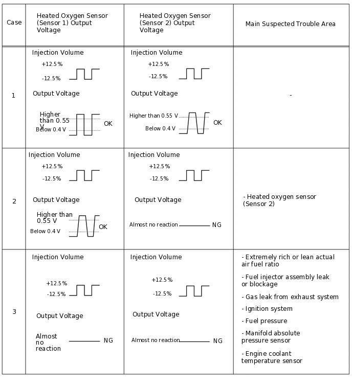
Perform the Active Test operation with the engine idling (press the RIGHT or LEFT button to change the fuel injection volume).
Monitor the voltage output of the heated oxygen sensor (sensor 1) and heated oxygen sensor (sensor 2) (O2S B1S1 and O2S B1S2) displayed on the GTS.
Tip:The Control the Injection Volume for A/F Sensor operation lowers the fuel injection volume by 12.5% or increases the injection volume by 12.5%.
The heated oxygen sensor (sensor 1) has an output delay of a few seconds and the heated oxygen sensor (sensor 2) has a maximum output delay of approximately 20 seconds.
If the sensor output voltage does not change (almost no reaction) while performing the Active Test, the sensor may be malfunctioning.
Result
The heated oxygen sensors reacts in accordance with increases and decreases of the fuel injection volume
+12.5% = Rich output
Higher than 0.55 V
-12.5% = Lean output
Below 0.4 V
The following procedure enables the technician to check and graph the voltage outputs of both the heated oxygen sensors.
To display the graph, enter the following menus:
Powertrain / Engine and ECT / Active Test / Control the Injection Volume for A/F Sensor / All Data / O2S B1S1 and O2S B1S2; then press the view button.
Tip:If the vehicle is short of fuel, the air fuel ratio becomes lean and the heated oxygen sensor DTCs are recorded, and then the MIL illuminates.
Result
Result
Proceed to
Case 2
A
Case 3
B
Case 1
C
CHECK HARNESS AND CONNECTOR (HEATED OXYGEN SENSOR (SENSOR 2) - ECM)
Disconnect the heated oxygen sensor (sensor 2) connector.
Disconnect the ECM connector.
Measure the resistance according to the value(s) in the table below.
Standard Resistance
Tester Connection
Condition
Specified Condition
B18-4 (OX1B) - B31-103 (OX1B)
Always
Below 1 Ω
B18-2 (HT1B) - B31-25 (HT1B)
Always
Below 1 Ω
B18-3 (E1) - B31-135 (E12)
Always
Below 1 Ω
B18-4 (OX1B) or B31-103 (OX1B) - Body ground
Always
10 kΩ or higher
B18-2 (HT1B) or B31-25 (HT1B) - Body ground
Always
10 kΩ or higher
Result
Proceed to
OK
NG
NG REPAIR OR REPLACE HARNESS OR CONNECTOR
REPLACE HEATED OXYGEN SENSOR (SENSOR 2)
Replace the heated oxygen sensor (sensor 2).
Result
Proceed to
NEXT
CHECK WHETHER DTC OUTPUT RECURS (DTC P0139)
Connect the GTS to the DLC3.
Turn the ignition switch to ON.
Turn the GTS on.
Clear the DTCs.
Powertrain > Engine and ECT > Clear DTCs
Turn the ignition switch off and wait for at least 30 seconds.
Start the engine and warm it up.
Turn the GTS on.
Drive the vehicle in accordance with the driving pattern described in Confirmation Driving Pattern.
Enter the following menus: Powertrain / Engine and ECT / Trouble Codes.
Read the pending DTCs.
Powertrain > Engine and ECT > Trouble Codes
Result
Result
Proceed to
DTCs are not output
A
DTC P0139 is output
B
A END
CHECK WHETHER MISFIRE OCCURS
Check the idling condition.
OK
Rough idling does not occur.
Result
Proceed to
OK
NG
CHECK FUEL PRESSURE
Check the fuel pressure.
Result
Proceed to
OK
NG
NG REPAIR OR REPLACE FUEL SYSTEM
INSPECT FUEL INJECTOR ASSEMBLY (INJECTION AND VOLUME)
Check the injector volume.
Result
Proceed to
OK
NG
OK CHECK FOR EXHAUST GAS LEAK
CHECK WHETHER DTC OUTPUT RECURS (DTC P0139)
Connect the GTS to the DLC3.
Turn the ignition switch to ON.
Turn the GTS on.
Clear the DTCs.
Powertrain > Engine and ECT > Clear DTCs
Turn the ignition switch off and wait for at least 30 seconds.
Start the engine and warm it up.
Turn the GTS on.
Drive the vehicle in accordance with the driving pattern described in Confirmation Driving Pattern.
Enter the following menus: Powertrain / Engine and ECT / Trouble Codes.
Read the pending DTCs.
Powertrain > Engine and ECT > Trouble Codes
Result
Result
Proceed to
DTC P0139 is output
A
DTCs are not output
B