NAVIGATION SYSTEM(for Radio and Display Type) TERMINALS OF ECU
Check from the rear of the connector while it is connected to the components.
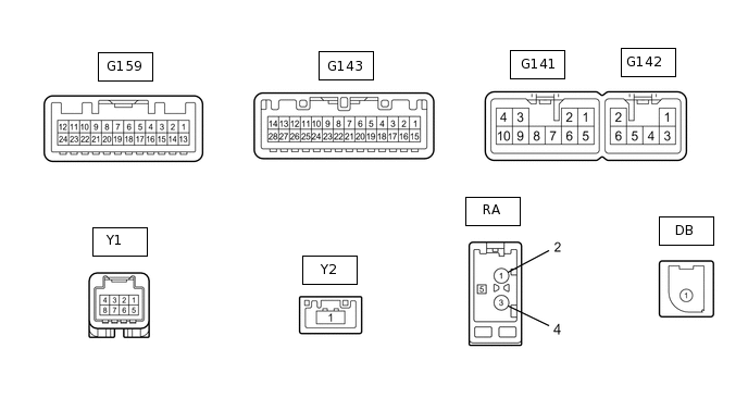
RADIO AND DISPLAY RECEIVER ASSEMBLY
Terminal No. (Symbol)
Wiring Color
Terminal Description
Condition
Specified Condition
G142-1 (RR+) - G141-7 (GND1)*1
R - BR
Sound signal (Right)
Audio system playing
A waveform synchronized with voice signals is output
G142-2 (RL+) - G141-7 (GND1)
B - BR
Sound signal (Left)
Audio system playing
A waveform synchronized with voice signals is output
G142-3 (RR-) - G141-7 (GND1)*1
W - BR
Sound signal (Right)
Audio system playing
A waveform synchronized with voice signals is output
G142-6 (RL-) - G141-7 (GND1)
Y - BR*1
W - BR*2
Sound signal (Left)
Audio system playing
A waveform synchronized with voice signals is output
G141-1 (FR+) - G141-7 (GND1)
LG - BR*1
B - BR*2
Sound signal (Right)
Audio system playing
A waveform synchronized with voice signals is output
G141-2 (FL+) - G141-7 (GND1)
P - BR*1
R - BR*2
Sound signal (Left)
Audio system playing
A waveform synchronized with voice signals is output
G141-3 (ACC1) - G141-7 (GND1)
GR - BR
Power source (ACC)
Ignition switch ACC
11 to 14 V*4
9.5 to 14 V*5
Ignition switch off
Below 1 V
G141-4 (+B1) - G141-7 (GND1)
SB - BR
Power source (+B)
Always
11 to 14 V*4
9.5 to 14 V*5
G141-5 (FR-) - G141-7 (GND1)
L - BR*1
W - BR*2
Sound signal (Right)
Audio system playing
A waveform synchronized with voice signals is output
G141-6 (FL-) - G141-7 (GND1)
V - BR*1
G - BR*2
Sound signal (Left)
Audio system playing
A waveform synchronized with voice signals is output
G141-7 (GND1) - Body ground
BR - Body ground
Ground
Always
Below 1 Ω
G141-10 (ILL+) - G141-7 (GND1)
G - BR
Illumination signal
Ignition switch ON, light control switch off → tail or head position
Below 1 V → 11 to 14 V
G143-1 (IG) - G141-7 (GND1)
Y - BR
Power source (IG)
Ignition switch ON
11 to 14 V
Ignition switch off
Below 1 V
G143-2 (REV) - G141-7 (GND1)
BE - BR
Reverse signal
See "Vehicle Signal Check Mode" in Operation Check
-
G143-4 (MACC) - G141-7 (GND1)
B - BR
Telephone microphone assembly power supply
Ignition switch off
Below 1 V
Ignition switch ACC
4 to 6 V
G143-5 (MIN+) - G141-7 (GND1)
W - BR
Microphone voice signal
See "Microphone & Voice Recognition Check" in Operation Check
-
G143-6 (SNS2) - G141-7 (GND1)
P - BR
Microphone connection detection signal
Always
Below 1 V
G143-7 (TX1+)*2
R
AVC-LAN communication signal
-
-
G143-8 (TX1-)*2
G
AVC-LAN communication signal
-
-
G143-9 (CANH)
Y
CAN communication signal
-
-
G143-10 (CANL)
W
CAN communication signal
-
-
G143-11 (AGND) - Body ground
Shielded - Body ground
Shield ground
Always
Below 1 V
G143-15 (PKB) - G141-7 (GND1)
B - BR
Parking brake signal
See "Vehicle Signal Check Mode" in Operation Check
-
G143-16 (MUT1) - G141-7 (GND1)*2
R - BR
Mute signal
Audio system playing
Above 3.5 V
Audio system changing modes
Below 1 V
G143-17 (SPD) - G141-7 (GND1)
BE - BR
Speed signal from combination meter assembly
See "Vehicle Signal Check Mode" in Operation Check
-
G143-18 (SGND) - G141-7 (GND1)
Shielded - BR
Shield ground
Always
Below 1 V
G143-19 (MIN-) - Body ground
R - Body ground
Microphone voice signal
See "Microphone & Voice Recognition Check" in Operation Check
-
G143-21 (SW1) - G143-23 (SWG)
W - B
Steering pad switch signal
No switch pushed
2.97 to 3.56 V
Up switch pushed
0.27 to 0.35 V
Up switch pushed
0.86 to 1.03 V
Volume+ switch pushed
1.51 to 1.79 V
Volume- switch pushed
2.22 to 2.66 V
G143-22 (SW2) - G143-23 (SWG)
R - B
Steering pad switch signal
No switch pushed
2.97 to 3.56 V
MODE/HOLD switch pushed
0.27 to 0.35 V
On hook switch pushed
0.86 to 1.03 V
Off hook switch pushed
1.51 to 1.79 V
Voice switch pushed
2.22 to 2.66 V
G143-23 (SWG) - Body ground
B - Body ground
Steering pad switch signal
Always
Below 1 V
G143-24 (SW3) - G143-23 (SWG)
G - B
Steering pad switch signal
No switch pushed
2.97 to 3.56 V
Enter switch pushed
0.27 to 0.35 V
Back switch pushed
0.86 to 1.03 V
Right switch pushed
1.51 to 1.79 V
Left switch pushed
2.22 to 2.66 V
G143-25 (ADPG) - G141-7 (GND1)
R - BR
External device connector detection signal
External device connected
Below 1 V
External device not connected
2.1 to 3 V
G143-26 (VAR+) - G143-27 (VA-)
W - R
Sound signal (Right)
AUX audio device playing (When stereo jack adapter used)
A waveform synchronized with voice signals is output
G143-27 (VA-) - G141-7 (GND1)
R - BR
Sound signal ground
Always
Below 1 V
G143-28 (VAL+) - G143-27 (VA-)
B - R
Sound signal (Left)
AUX audio device playing (When stereo jack adapter used)
A waveform synchronized with sound signals is output
Y1-1 (SLD4) - Body ground
B - Body ground
Shield ground
Always
Below 1 V
Y1-2 (SPDO) - G141-7 (GND1)
B - BR
Vehicle speed signal
See "Check Vehicle Signal" in Operation Check
-
Y1-3 (ACC2) - G141-7 (GND1)
B - BR
Power source (ACC)
Ignition switch off
Below 1 V
Ignition switch ACC
11 to 14 V
Y1-4 (+B2) - G141-7 (GND1)
W - BR
Power source (+B)
Always
11 to 14 V
Y1-5 (MIC+) - G141-7 (GND1)
B - BR
Microphone voice signal
See "Microphone & Voice Recognition Check" in Operation Check
-
Y1-6 (MIC-) - G141-7 (GND1)
B - BR
Microphone voice signal
See "Microphone & Voice Recognition Check" in Operation Check
-
Y1-8 (GND2) - Body ground
W - Body ground
Ground
Always
-
Y2-1 (LVDS)
#
LVDS communication signal
-
-
DB-1 (DAB)*3
#
DAB antenna
-
-
RA-5 (ANT+) - Body ground
# - Body ground
Power source of antenna
Ignition switch ACC
Radio switch on and AM or FM selected
11 to 14 V
*1: for 6 Speakers
*2: for 11 Speakers
*3: w/ DAB Function
*4: w/o Stop and Start System
*5: w/ Stop and Start System
#: There is no wire color information
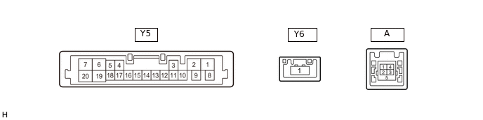
NAVIGATION ECU
Terminal No. (Symbol)
Wiring Color
Terminal Description
Condition
Specified Condition
Y5-1 (B+) - Y5-2 (GND)
W - W
Power source (+B)
Always
11 to 14 V
Y5-2 (GND) - Body ground
W - Body ground
Ground
Always
Below 1 V
Y5-3 (ACC) - Y5-2 (GND)
B - W
Power source (ACC)
Ignition switch off
Below 1 V
Ignition switch ACC
11 to 14 V
Y5-5 (SPD) - Y5-2 (GND)
B - W
Vehicle speed signal
Ignition switch ON Wheel being rotated
Pulse generation
Y5-16 (MIC+) - Y5-2 (GND)
B - W
Microphone voice signal
See "Microphone & Voice Recognition Check" in Operation Check
-
Y5-17 (MIC-) - Y5-2 (GND)
B - W
Microphone voice signal
See "Microphone & Voice Recognition Check" in Operation Check
-
Y5-18 (MSHLD) - Body ground
B - Body ground
Shield ground
Always
Below 1 V
A-1 (USV1)
#
Power source
-
-
A-2 (US1-)
#
Data signal
-
-
A-3 (US1+)
#
Data signal
-
-
A-4 (UGD1)
#
Ground
-
-
A-5 (USG1)
Shielded
Shield ground
-
-
Y6-1 (LVDS)
#
LVDS communication signal
-
-
#: There is no wire color information
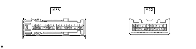
STEREO COMPONENT AMPLIFIER ASSEMBLY
Terminal No. (Symbol)
Wiring Color
Terminal Description
Condition
Specified Condition
M33-1 (+B) - M33-3 (GND)
W - W-B
Power source (+B)
Always
11 to 14 V
M33-3 (GND) - Body ground
W-B - Body ground
Ground
Always
Below 1 Ω
M33-8 (WFL+) - M33-3 (GND)
B - W-B
Sound signal (Woofer)
Audio system playing
A waveform synchronized with sound is output
M33-15 (WFR+) - M33-3 (GND)
P - W-B
Sound signal (Woofer)
Audio system playing
A waveform synchronized with sound is output
M33-11 (RL+) - M33-3 (GND)
B - W-B
Sound signal (Rear Left)
Audio system playing
A waveform synchronized with sound is output
M33-12 (RR+) - M33-3 (GND)
R - W-B
Sound signal (Front Right)
Audio system playing
A waveform synchronized with sound is output
M33-14 (FL+) - M33-3 (GND)
P - W-B
Sound signal (Front Left)
Audio system playing
A waveform synchronized with sound is output
M33-13 (TWR+) - M33-3 (GND)
Y - W-B
Sound signal (Front Right)
Audio system playing
A waveform synchronized with sound is output
M33-10 (TWL+) - M33-3 (GND)
P - W-B
Sound signal (Front Left)
Audio system playing
A waveform synchronized with sound is output
M33-9 (FR+) - M33-3 (GND)
LG - W-B
Sound signal (Front Right)
Audio system playing
A waveform synchronized with sound is output
M33-23 (WFL-) - M33-3 (GND)
G - W-B
Sound signal (Woofer)
Audio system playing
A waveform synchronized with sound is output
M33-30 (WFR-) - M33-3 (GND)
V - W-B
Sound signal (Woofer)
Audio system playing
A waveform synchronized with sound is output
M33-26 (RL-) - M33-3 (GND)
Y - W-B
Sound signal (Rear Left)
Audio system playing
A waveform synchronized with sound is output
M33-27 (RR-) - M33-3 (GND)
W - W-B
Sound signal (Rear Right)
Audio system playing
A waveform synchronized with sound is output
M33-29 (FL-) - M33-3 (GND)
V - W-B
Sound signal (Front Left)
Audio system playing
A waveform synchronized with sound is output
M33-28 (TWR-) - M33-3 (GND)
B - W-B
Sound signal (Front Right)
Audio system playing
A waveform synchronized with sound is output
M33-25 (TWL-) - M33-3 (GND)
V - W-B
Sound signal (Front Left)
Audio system playing
A waveform synchronized with sound is output
M33-24 (FR-) - M33-3 (GND)
L - W-B
Sound signal (Front Right)
Audio system playing
A waveform synchronized with sound is output
M32-1 (MUTE) - M33-3 (GND)
R - W-B
Mute signal
Audio system playing
3.5 V or higher
Audio system changing modes
Below 1 V
M32-2 (L-) - M33-3 (GND)
G - W-B
Sound signal (Left)
Audio system playing
A waveform synchronized with sound is output
M32-3 (L+) - M33-3 (GND)
R - W-B
Sound signal (Left)
Audio system playing
A waveform synchronized with sound is output
M32-4 (R-) - M33-3 (GND)
W - W-B
Sound signal (Right)
Audio system playing
A waveform synchronized with sound is output
M32-5 (R+) - M33-3 (GND)
B - W-B
Sound signal (Right)
Audio system playing
A waveform synchronized with sound is output
M32-6 (SLD) - Body ground
Shield - Body ground
Shield ground
Always
Below 1 Ω
M32-7 (TX-)
G
AVC-LAN communication signal
-
-
M32-8 (TX+)
R
AVC-LAN communication signal
-
-
M32-11 (SPD) - M33-3 (GND)
L - W-B
Vehicle speed signal
Ignition switch ON
Wheel being rotated
Pulse generation
M32-12 (ACC) - M33-3 (GND)
GR - W-B
Power source (ACC)
Ignition switch off
Below 1 V
Ignition switch ACC
11 to 14 V
M32-14 (II1-) - M33-3 (GND)
W - W-B
Voice signal
Voice guidance sounding
A waveform synchronized with sound is output
M32-15 (II1+) - M33-3 (GND)
B - W-B
Voice signal
Voice guidance sounding
A waveform synchronized with sound is output
M32-18 (SLD1) - Body ground
Shield - Body ground
Shield ground
Always
Below 1 Ω