ENGINE UNIT DISASSEMBLY
PROCEDURE
PRECAUTION
Note:After the engine has stopped, wait at least 1 minute before releasing the high pressure lines.
When working on the fuel circuit, protect the generator assembly against contamination. Cover the generator assembly with suitable materials. Failure to comply with this procedure may result in a generator assembly malfunction.
-
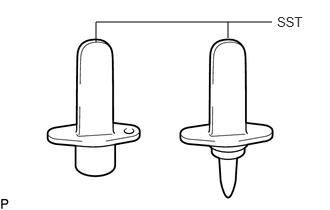
After disconnecting the pressure line, it is absolutely essential to seal the injector assemblies and the common rail assembly with SST.
SST
PZ4TB-04941-79
REMOVE CAMSHAFT POSITION SENSOR
REMOVE CRANKSHAFT POSITION SENSOR
REMOVE ENGINE COOLANT TEMPERATURE SENSOR
REMOVE ENGINE OIL PRESSURE SWITCH ASSEMBLY
REMOVE NOZZLE LEAKAGE PIPE ASSEMBLY
REMOVE INJECTOR ASSEMBLY
REMOVE ENGINE WATER PUMP ASSEMBLY
REMOVE WATER BY-PASS PIPE
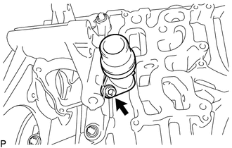
Using a 5 mm hexagon socket wrench, remove the bolt and water by-pass pipe from the water inlet housing.
REMOVE WATER INLET
REMOVE THERMOSTAT
REMOVE WATER INLET HOUSING
-
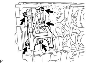
Using an E11 "TORX" socket wrench, remove the 5 bolts and water inlet housing.
-
REMOVE WATER OUTLET
-
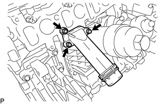
Using an E10 "TORX" socket wrench, remove the 3 bolts and water outlet.
Remove the gasket from the water outlet.
-
REMOVE OIL FILTER SUB-ASSEMBLY
REMOVE OIL FILTER ASSEMBLY
SET NO. 1 CYLINDER TO TDC/COMPRESSION
REMOVE OIL FILLER CAP SUB-ASSEMBLY
Remove the oil filler cap sub-assembly from the cylinder head cover sub-assembly.
REMOVE CYLINDER HEAD COVER SUB-ASSEMBLY
SECURE CAMSHAFT AND NO. 2 CAMSHAFT
REMOVE NO. 2 CHAIN TENSIONER ASSEMBLY
REMOVE NO. 2 TIMING CHAIN GUIDE
REMOVE CAMSHAFT AND NO. 2 CAMSHAFT
REMOVE CAMSHAFT HOUSING SUB-ASSEMBLY
REMOVE NO. 1 VALVE ROCKER ARM SUB-ASSEMBLY
REMOVE VALVE LASH ADJUSTER ASSEMBLY
REMOVE CYLINDER HEAD SUB-ASSEMBLY
REMOVE CYLINDER HEAD GASKET
REMOVE CRANKSHAFT PULLEY
REMOVE TIMING GEAR CASE OR TIMING CHAIN CASE OIL SEAL
REMOVE CLUTCH COVER ASSEMBLY
REMOVE CLUTCH DISC ASSEMBLY
REMOVE FLYWHEEL WITH DAMPER ASSEMBLY
REMOVE FUEL SUPPLY PUMP ASSEMBLY
-
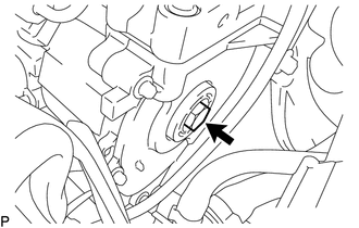
Remove the sealing cap from the timing chain cover plate.
Remove the O-ring from the sealing cap.
-
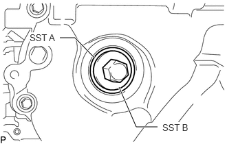
Using SST (B), install SST (A) to position the fuel supply pump assembly. Then remove SST (B).
SST
PZ4TB-04967-25
Note:Do not remove SST (A) from the timing chain cover plate until all repair work has been completed.
-
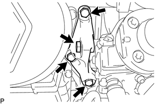
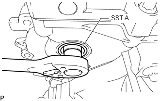
Remove the 4 bolts and fuel supply pump assembly support.
-
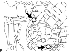
Remove the 2 bolts from the fuel supply pump assembly.
-
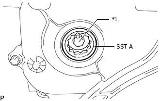
*1
Central Bolt
Loosen the central bolt connection between the fuel supply pump assembly and injection pump drive gear.
Note:Do not remove SST (A) from the timing chain cover plate.
The central bolt is supported on SST (A) until the fuel supply pump assembly is pressed out.
Do not remove the central bolt from SST (A) until all repair work has been completed.
Remove the fuel supply pump assembly from the cylinder block.
-
REMOVE OIL PAN SUB-ASSEMBLY
REMOVE OIL STRAINER SUB-ASSEMBLY
REMOVE OIL PUMP WITH VACUUM PUMP ASSEMBLY
REMOVE REAR ENGINE OIL SEAL
REMOVE TIMING CHAIN COVER PLATE
-
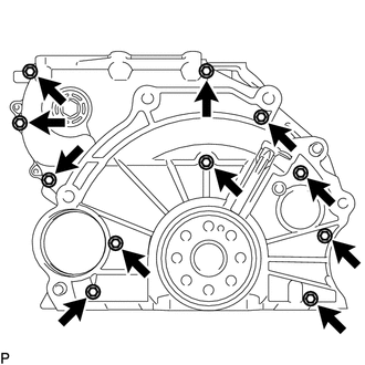
Using an E8 "TORX" socket wrench, remove the 11 bolts and timing chain cover plate.
-
REMOVE OIL PUMP DRIVE CHAIN SUB-ASSEMBLY
-
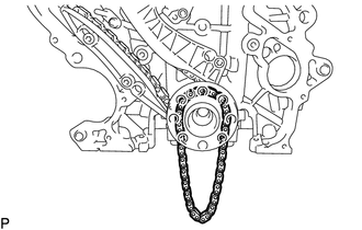
Remove the oil pump drive chain sub-assembly from the crankshaft.
-
REMOVE NO. 2 CHAIN SUB-ASSEMBLY
-
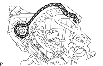
Remove the No. 2 chain sub-assembly from the injection pump drive gear.
-
REMOVE NO. 2 TIMING CHAIN TENSION ARM
-
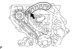
Using a T45 "TORX" socket wrench, remove the bolt and No. 2 timing chain tension arm.
-
REMOVE NO. 1 CHAIN TENSIONER ASSEMBLY
-
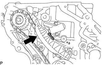
*a
Hexagon Wrench
Slowly push the plunger deep into the No. 1 chain tensioner assembly and insert a 3.0 mm hexagon wrench into the No. 1 chain tensioner assembly.
-
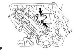
Using an E8 "TORX" socket wrench, remove the 2 bolts and No. 1 chain tensioner assembly.
-
REMOVE TIMING CHAIN TENSION ARM
-
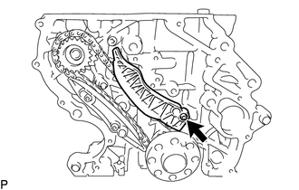
Using a T45 "TORX" socket wrench, remove the bolt and timing chain tension arm.
-
REMOVE TIMING CHAIN GUIDE
-
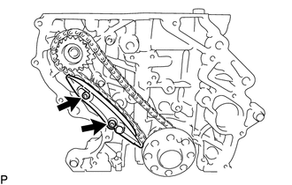
Using a T45 "TORX" socket wrench, remove the 2 bolts and timing chain guide.
-
REMOVE INJECTION PUMP DRIVE GEAR
-
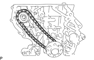
Remove the injection pump drive gear and chain sub-assembly.
-
REMOVE NO. 2 OIL NOZZLE SUB-ASSEMBLY
-
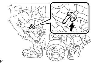
Using an E8 "TORX" socket wrench, remove the bolt and No. 2 oil nozzle sub-assembly.
-