FRONT SUSPENSION SYSTEM
-
OUTLINE
-
A MacPherson strut type independent suspension is used.
-
Excellent driving stability and ride comfort are achieved by optimizing the suspension geometry.
-
A split-input type structure is adopted for the front suspension support sub-assembly to ensure excellent quietness and ride comfort.
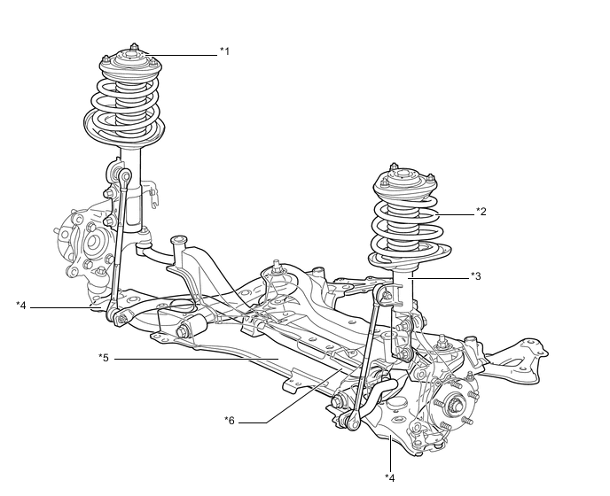
Text in Illustration *1 Front Suspension Support Sub-assembly *2 Front Coil Spring *3 Front Shock Absorber Assembly *4 Front Lower No. 1 Suspension Arm Sub-assembly *5 Suspension Member (Front Suspension Crossmember Sub-assembly) *6 Front Stabilizer Bar
-
-
MAIN FEATURES
-
Optimized Caster
-
Optimum caster angle and trail values are featured to provide straight-line stability during low-speed to high-speed ranges and assist steering response at high speeds.
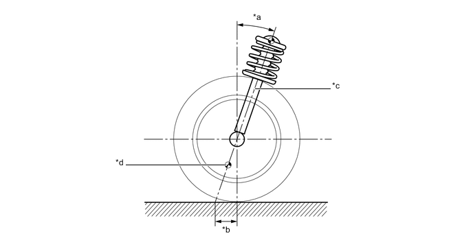
Text in Illustration *a Caster Angle *b Trail Value *c King Pin Axis *d Lower Ball Joint Fulcrum Point
-
-
Optimized Camber
-
The front suspension uses negative camber to reduce the ground contact camber angle of the outer wheel at the time of turning (cornering) which is caused when the vehicle posture changes during cornering, thus realizing excellent cornering performance.
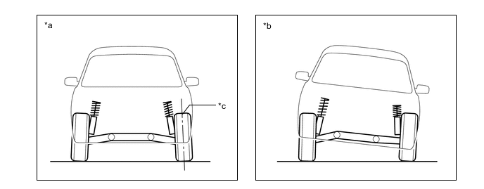
Text in Illustration *a Straight-line *b Cornering *c Negative Camber - -
-
-
Optimized King Pin Offset
-
A small king pin offset is used to reduce the moment which occurs around the king pin axis in order to achieve excellent vehicle stability during braking. When force is applied to the wheel, such as while braking, force is applied at the tire center ground contact point and the king pin offset. Because of the distance between the king pin offset and the tire centerline, this force tries to turn the king pin axis. In this way, making the king pin offset smaller produces a smaller moment at the king pin axis, providing excellent vehicle stability during braking.
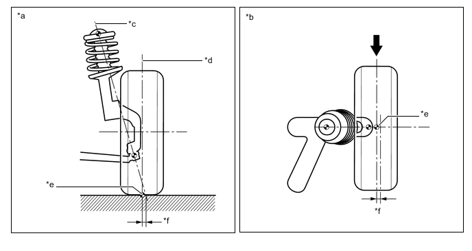
Text in Illustration *a Rear View *b Top View *c King Pin Axis *d Tire Contact Center *e Tire Center Ground Contact Point *f King Pin Offset 
Force - -
-
-