CRUISE CONTROL SYSTEM TC and CG Terminal Circuit
DESCRIPTION
Connecting terminals TC and CG of the DLC3 enables DTCs to be read through blinking patterns of the combination meter's cruise control indicator light.
Tech Tips
When a warning light of the combination meter blinks continuously, terminal TC of the DLC3 or an ECM may have a ground short.
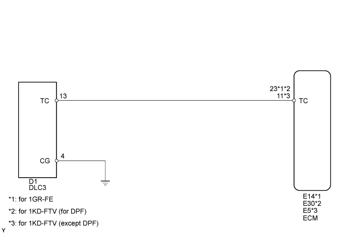
WIRING DIAGRAM
INSPECTION PROCEDURE
PROCEDURE
-
CHECK HARNESS AND CONNECTOR (DLC3 - ECM AND BODY GROUND)
-
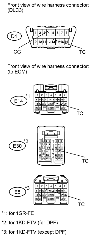
Disconnect the D1 DLC3 connector.
-
Disconnect the E14*1, E30*2 or E5*3 ECM connector.
-
*1: for 1GR-FE
-
*2: for 1KD-FTV (for DPF)
-
*3: for 1KD-FTV (except DPF)
-
-
Measure the resistance according to the value(s) in the table below.
Standard Resistance for 1GR-FE Tester Connection Specified Condition D1-13 (TC) - E14-23 (TC) Below 1 Ω D1-13 (TC) - Body ground 10 kΩ or higher D1-4 (CG) - Body ground Below 1 Ω for 1KD-FTV (for DPF) Tester Connection Specified Condition D1-13 (TC) - E30-23 (TC) Below 1 Ω D1-13 (TC) - Body ground 10 kΩ or higher D1-4 (CG) - Body ground Below 1 Ω for 1KD-FTV (except DPF) Tester Connection Specified Condition D1-13 (TC) - E5-11 (TC) Below 1 Ω D1-13 (TC) - Body ground 10 kΩ or higher D1-4 (CG) - Body ground Below 1 Ω
NG 
REPAIR OR REPLACE HARNESS OR CONNECTOR
OK 
REPLACE ECM
-