THERMOSTAT (w/ EGR Cooler) INSTALLATION
-
INSTALL THERMOSTAT
-
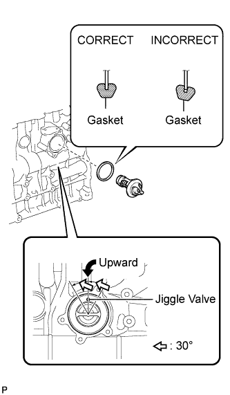
Install a new gasket to the thermostat.
Tech Tips
When installing the thermostat to the gasket, be careful not to deform the gasket. Make sure that the thermostat is properly installed into the groove of the gasket, as shown in the illustration.
-
Insert the thermostat into the cylinder block with the jiggle valve facing straight upward.
Tech Tips
The jiggle valve may be set within 30°of either side of the prescribed position.
-
-
INSTALL WATER INLET
-
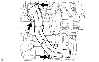
Install the water inlet with the 3 bolts.
- Torque:
- 13 N*m { 133 kgf*cm, 10 ft.*lbf }
-
-
CONNECT NO. 1 AUTOMATIC TRANSMISSION OIL COOLER TUBE CLAMP (for Automatic Transmission)
-
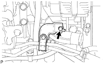
Connect the No. 1 automatic transmission oil cooler tube clamp to the water inlet with the bolt.
- Torque:
- 12 N*m { 122 kgf*cm, 9 ft.*lbf }
-
-
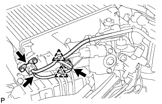
INSTALL COMPRESSOR INLET ELBOW (for LHD)
-
Install the No. 12 water by-pass hose to the compressor inlet elbow.
-
Install the No. 7 water by-pass hose to the compressor inlet elbow.
-
Install a new gasket and the compressor inlet elbow with the 2 nuts.
- Torque:
- 19 N*m { 194 kgf*cm, 14 ft.*lbf }
-
Connect the No. 13 water by-pass hose to the No. 2 water by-pass pipe sub-assembly.
-
Connect the No. 2 water by-pass hose and the No. 1 turbo water pipe sub-assembly.
-
Connect the No. 1 turbo water hose to the cylinder block.
-
Connect the 2 connectors and attach the wire harness clamp.
-
-
INSTALL COMPRESSOR INLET ELBOW (for RHD)
-
Connect the 2 No. 1 turbo water hoses to the No. 2 water by-pass pipe sub-assembly and the cylinder block.
-
Install a new gasket and inlet elbow with the 2 nuts.
- Torque:
- 19 N*m { 194 kgf*cm, 14 ft.*lbf }
-
Connect the 2 connectors and attach the wire harness clamp.
-
-
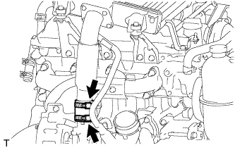
INSTALL VENTILATION PIPE
-
Install the ventilation pipe with the bolt.
- Torque:
- 20 N*m { 204 kgf*cm, 15 ft.*lbf }
-
for LHD:
Connect the No. 12 water by-pass hose and No. 13 water by-pass hose.
-
-
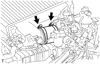
CONNECT RADIATOR HOSE OUTLET
-
Connect the radiator hose outlet to the water inlet.
-
-
INSTALL INTERCOOLER ASSEMBLY
-
Install the intake air connector to the air hoses.
-
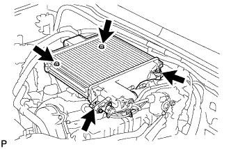
Install the intercooler with the 4 bolts.
- Torque:
- 12 N*m { 122 kgf*cm, 9 ft.*lbf }
-
Install a new No. 2 air hose and then tighten the 2 hose clamps.
- Torque:
- 6.5 N*m { 66 kgf*cm, 58 in.*lbf }
-
Tighten the 2 hose clamps of the No. 1 air hose.
- Torque:
- 6.5 N*m { 66 kgf*cm, 58 in.*lbf }
-
Connect the IAT sensor connector and manifold absolute diesel pressure sensor connector.
-
Connect the vacuum hose to the manifold absolute pressure sensor.
-
Attach the 2 clamps.
-
-
INSTALL NO. 1 ENGINE COVER SUB-ASSEMBLY
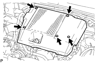
-
Install the engine cover with the 3 bolts and 2 nuts.
- Torque:
- 7.0 N*m { 71 kgf*cm, 62 in.*lbf }
-
-
INSTALL AIR CLEANER ASSEMBLY
-
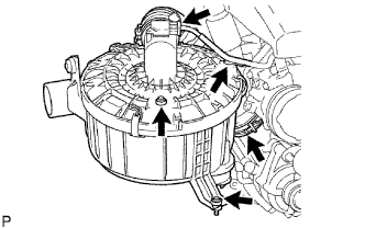
Install the air cleaner assembly with the 2 bolts.
- Torque:
- 14 N*m { 143 kgf*cm, 10 ft.*lbf }
-
Tighten the hose clamp of the compressor inlet elbow.
-
Connect the mass air flow meter connector and install the clamp.
-
-
CONNECT CABLE TO NEGATIVE BATTERY TERMINAL
-
ADD ENGINE COOLANT
-
Tighten the cylinder block drain cock plug.
- Torque:
- 8.0 N*m { 82 kgf*cm, 71 in.*lbf }
-
Tighten the radiator drain cock plug by hand.
-
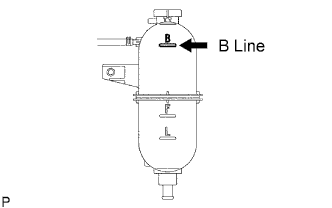
Fill the radiator with TOYOTA Super Long Life Coolant (SLLC) to the reservoir tank's B line.
Standard capacity Item Specified Condition A/T 11.1 liters (11.7 US qts, 9.8 Imp. qts) M/T 9.8 liters (10.4 US qts, 8.6 Imp. qts) Tech Tips
TOYOTA vehicles are filled with TOYOTA SLLC at the factory. In order to avoid damage to the engine cooling system and other technical problems, only use TOYOTA SLLC or similar high quality ethylene glycol based non-silicate, non-amine, non-nitrite, non-borate coolant with long-life hybrid organic acid technology (coolant with long-life hybrid organic acid technology consists of a combination of low phosphates and organic acids).
Note
Never use water as a substitute for engine coolant.
-
Press the inlet and outlet radiator hoses several times by hand, and then check the level of the coolant.
If the coolant level drops below the B line, add TOYOTA SLLC to the B line.
-
Install the radiator reservoir cap.
-

Using a wrench, install the vent plug.
- Torque:
- 2.0 N*m { 20 kgf*cm, 18 in.*lbf }
-
Bleed air from the cooling system.
-
Warm up the engine until the thermostat opens. While the thermostat is open, circulate the coolant for several minutes.
Tech Tips
The thermostat open timing can be confirmed by pressing the inlet radiator hose by hand, and checking when the engine coolant starts to flow inside the hose.
-
Maintain the engine speed at 2500 to 3000 rpm.
-
Press the inlet and outlet radiator hoses several times by hand to bleed air.
CAUTION:
When pressing the radiator hoses:
-
Wear protective gloves.
-
Be careful as the radiator hoses are hot.
-
Keep your hands away from the radiator fan.
-
-
Stop the engine and wait until the coolant cools down to ambient temperature.
CAUTION:
Do not remove the radiator reservoir cap while the engine and radiator are still hot. Pressurized, hot engine coolant and steam may be released and cause serious burns.
-
-
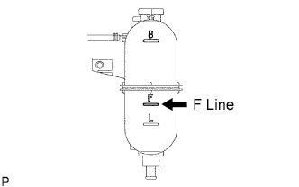
After the coolant cools down, check that the coolant level is at the F line.
If the coolant level is below the F line, add TOYOTA SLLC to the F line.
-
-
INSPECT FOR COOLANT LEAK
Note
Do not remove the radiator reservoir cap while the engine and radiator are still hot. Pressurized, hot engine coolant and steam may be released and cause serious burns.
-
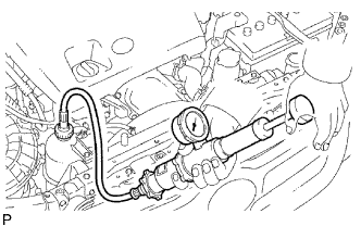
Fill the radiator with coolant and attach a radiator cap tester to the radiator reservoir.
-
Warm up the engine.
-
Using a radiator cap tester, increase the pressure inside the radiator to 118 kPa (1.2 kgf/cm2, 17.1 psi), and check that the pressure does not drop.
If the pressure drops, check the hoses, radiator and water pump for leaks.
If no external leaks are found, check the cylinder block and head.
-
-
INSTALL NO. 1 ENGINE UNDER COVER (for 4WD)
-
PERFORM INITIALIZATION
-
Perform initialization Click here.
Note
Certain systems need to be initialized after disconnecting and reconnecting the cable from the negative (-) battery terminal.
-