КЛАПАН ПРИНУДИТЕЛЬНОЙ ВЕНТИЛЯЦИИ КАРТЕРА УСТАНОВКА
-
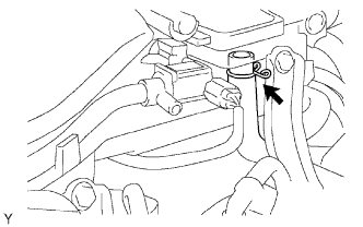
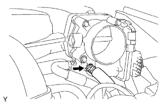
INSTALL VENTILATION VALVE SUB-ASSEMBLY
-
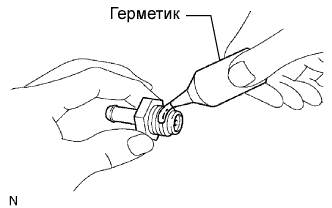
Apply adhesive to 2 or 3 threads of the valve.
Adhesive Toyota Genuine Adhesive 1324, Three Bond 1324 or equivalent -
Install the valve.
- Torque:
- 5.0 N*m { 51 kgf*cm, 44 in.*lbf }
-
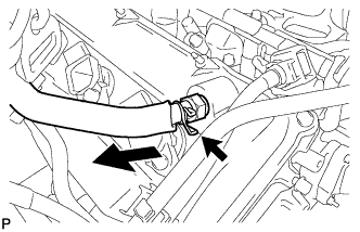
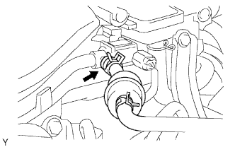
Connect the ventilation hose to the valve.
-
Secure the hose with the clamp.
-
-
INSTALL INTAKE AIR SURGE TANK
-
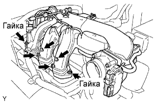
Install a new gasket and the surge tank with the 2 nuts.
- Torque:
- 28 N*m { 286 kgf*cm, 21 ft.*lbf }
-
Using an 8 hexagon wrench, install the 4 bolts.
- Torque:
- 28 N*m { 286 kgf*cm, 21 ft.*lbf }
-
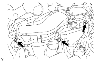
Install the 3 upper bolts which are used to secure the 2 surge tank stays and throttle body bracket.
- Torque:
- 21 N*m { 214 kgf*cm, 16 ft.*lbf }
-
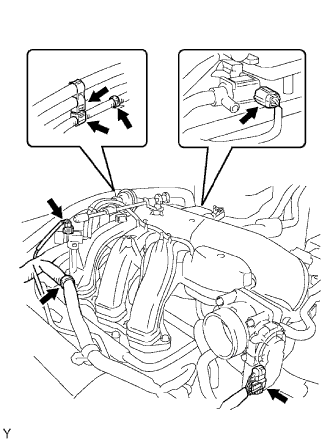
Install the 3 wire harness clamps and hose clamp.
-
Connect the throttle motor connector.
-
Connect the 2 VSV connectors.
-
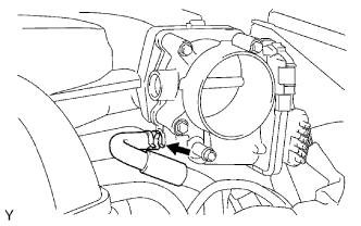
Connect the ventilation hose.
-
Connect the vapor feed hose assembly.
-
Connect the No. 4 water by-pass hose.
-
Connect the No. 5 water by-pass hose.
-
-
INSTALL V-BANK COVER
-
Install the cover with the 2 nuts.
- Torque:
- 7.5 N*m { 76.5 kgf*cm, 66 in.*lbf }
-
-
CONNECT CABLE TO NEGATIVE BATTERY TERMINAL
-
PERFORM INITIALIZATION
-
Perform initialization Click here.
Note
Certain systems need to be initialized after disconnecting and reconnecting the cable from the negative (-) battery terminal.
-