CAN COMMUNICATION SYSTEM(w/o Central Gateway ECU) ECM Communication Stop Mode
| DTC Code | DTC Name |
|---|---|
| ECM Communication Stop Mode |
DESCRIPTION
Detection Item |
Symptom |
Trouble Area |
|---|---|---|
ECM Communication Stop Mode |
Either condition is met:
|
|
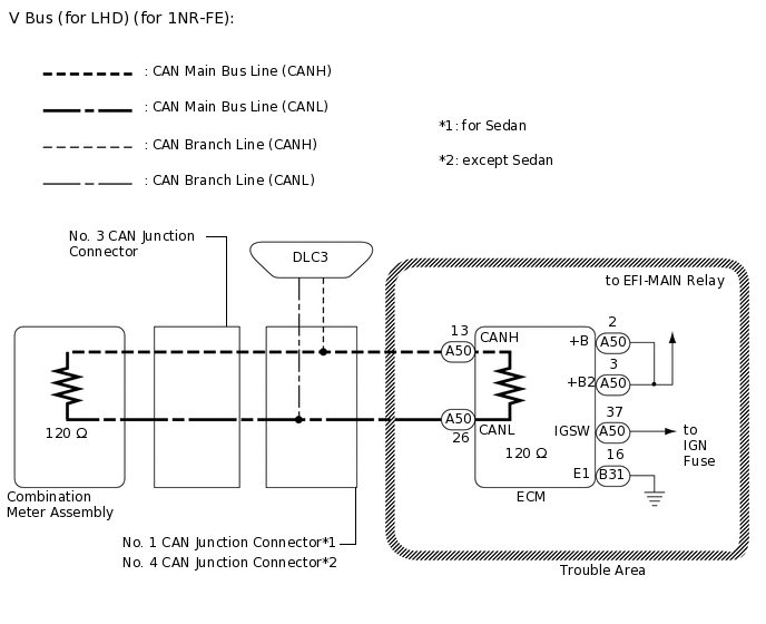
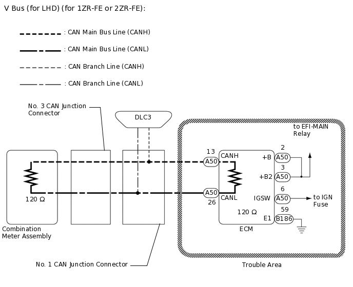
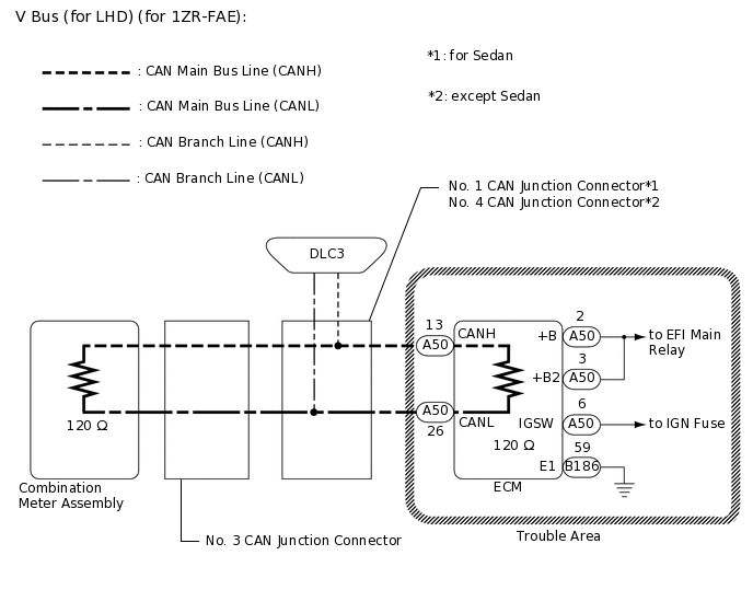
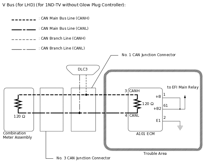
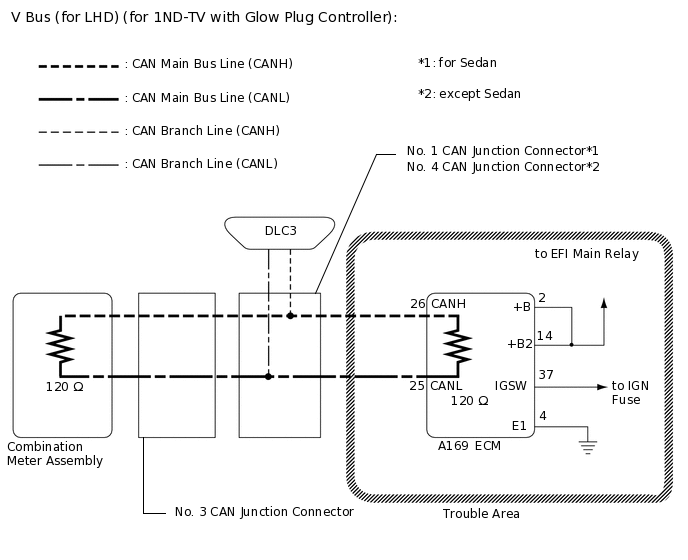
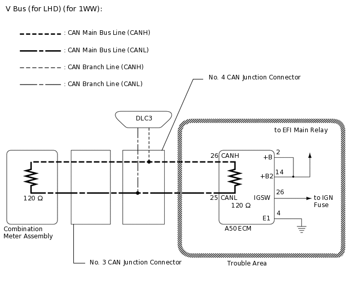
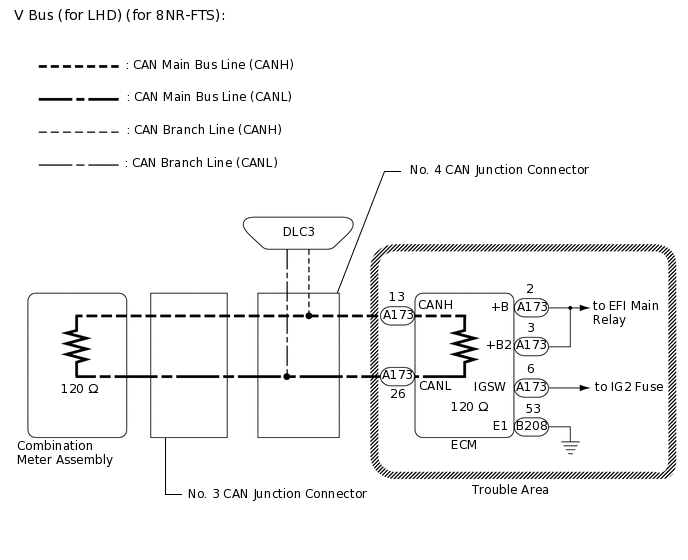
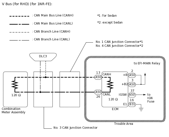
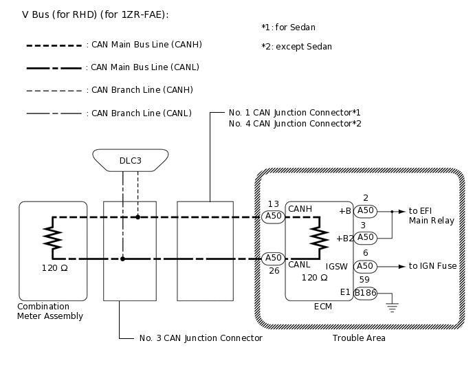
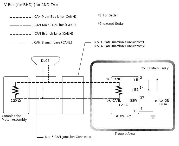
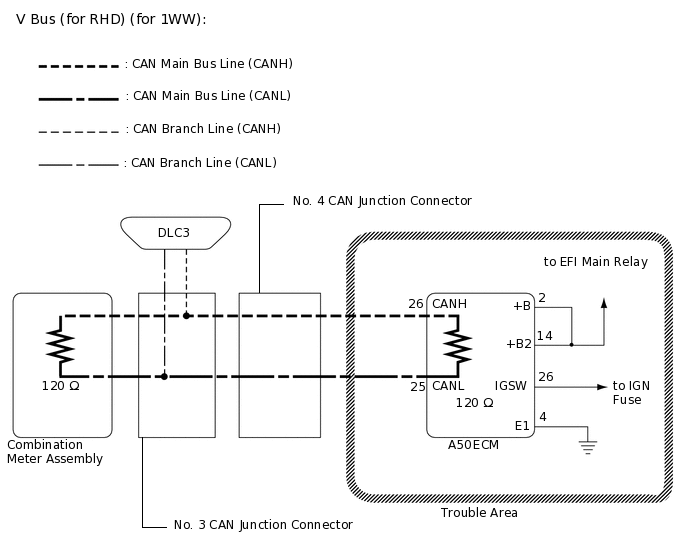
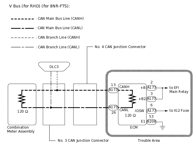
WIRING DIAGRAM
CAUTION / NOTICE / HINT
Before measuring the resistance of the CAN bus, turn the ignition switch off and leave the vehicle for 1 minute or more without operating the key or any switches, or opening or closing the doors. After that, disconnect the cable from the negative (-) battery terminal and leave the vehicle for 1 minute or more before measuring the resistance.
After turning the ignition switch off, waiting time may be required before disconnecting the cable from the negative (-) battery terminal. Therefore, make sure to read the disconnecting the cable from the negative (-) battery terminal notices before proceeding with work.
Because the order of diagnosis is important to allow correct diagnosis, make sure to begin troubleshooting using How to Proceed with Troubleshooting when CAN communication system related DTCs are output.
After performing repairs, perform the DTC check procedure and confirm that the DTCs are not output again.
DTC check procedure: Turn the ignition switch to ON and wait 20 seconds or more, and then drive the vehicle at a speed of 20 km/h (12 mph) or more.
After the repair, perform the CAN bus check and check that all the ECUs and sensors connected to the CAN communication system are displayed.
Inspect the fuses for circuits related to this system before performing the following procedure.
Operating the ignition switch, any other switches or a door triggers related ECU and sensor communication on the CAN. This communication will cause the resistance value to change.
Even after DTCs are cleared, if a DTC is stored again after driving the vehicle for a while, the malfunction may be occurring due to vibration of the vehicle. In such a case, wiggling the ECUs or wire harness while performing the inspection below may help determine the cause of the malfunction.
PROCEDURE
CHECK VEHICLE TYPE
Check vehicle type.
Result
Result
Result
Proceed to
for 1NR-FE, 1ZR-FAE, 1ZR-FE or 2ZR-FE
A
for 1ND-TV without Glow Plug Controller
B
for 1ND-TV with Glow Plug Controller
C
for 1WW
D
for 8NR-FTS
E
B CHECK FOR OPEN IN CAN BUS LINES (ECM MAIN LINE)Click here
C CHECK FOR OPEN IN CAN BUS LINES (ECM MAIN LINE)Click here
D CHECK FOR OPEN IN CAN BUS LINES (ECM MAIN LINE)Click here
E CHECK FOR OPEN IN CAN BUS LINES (ECM MAIN LINE)Click here
CHECK FOR OPEN IN CAN BUS LINES (ECM MAIN LINE)
Disconnect the cable from the negative (-) battery terminal.
-

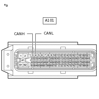
*a
Front view of wire harness connector
(to ECM)
Disconnect the A50 ECM connector.
Measure the resistance according to the value(s) in the table below.
Standard Resistance
Tester Connection
Condition
Specified Condition
A50-13 (CANH) - A50-26 (CANL)
Cable disconnected from negative (-) battery terminal
108 to 132 Ω
Result
Result
Result
OK
NG
NG REPAIR OR REPLACE CAN MAIN BUS LINE OR CONNECTOR (ECM MAIN LINE)
CHECK ECM POWER SOURCE CIRCUIT
Check the ECM power source circuit.
for 1NR-FE
for 1ZR-FAE
for 1ZR-FE
for 2ZR-FE
Result
Result
Proceed to
OK (for 1NR-FE)
A
OK (for 1ZR-FAE)
B
OK (for 1ZR-FE)
C
OK (for 2ZR-FE)
D
NG
E
E REPAIR OR REPLACE HARNESS OR CONNECTOR (POWER SOURCE CIRCUIT)
CHECK FOR OPEN IN CAN BUS LINES (ECM MAIN LINE)
Disconnect the cable from the negative (-) battery terminal.
-
*a
Front view of wire harness connector
(to ECM)
Disconnect the A101 ECM connector.
Measure the resistance according to the value(s) in the table below.
Standard Resistance
Tester Connection
Condition
Specified Condition
A101-3 (CANH) - A101-4 (CANL)
Cable disconnected from negative (-) battery terminal
108 to 132 Ω
Result
Result
Result
OK
NG
NG REPAIR OR REPLACE CAN MAIN BUS LINE OR CONNECTOR (ECM MAIN LINE)
CHECK ECM POWER SOURCE CIRCUIT
Check the ECM power source circuit.
Result
Result
Result
OK
NG
NG REPAIR OR REPLACE HARNESS OR CONNECTOR (POWER SOURCE CIRCUIT)
CHECK FOR OPEN IN CAN BUS LINES (ECM MAIN LINE)
Disconnect the cable from the negative (-) battery terminal.
-
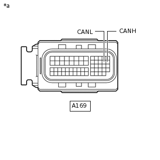
*a
Front view of wire harness connector
(to ECM)
Disconnect the A169 ECM connector.
Measure the resistance according to the value(s) in the table below.
Standard Resistance
Tester Connection
Condition
Specified Condition
A169-26 (CANH) - A169-25 (CANL)
Cable disconnected from negative (-) battery terminal
108 to 132 Ω
Result
Result
Result
OK
NG
NG REPAIR OR REPLACE CAN MAIN BUS LINE OR CONNECTOR (ECM MAIN LINE)
CHECK ECM POWER SOURCE CIRCUIT
Check the ECM power source circuit.
Result
Result
Result
OK
NG
NG REPAIR OR REPLACE HARNESS OR CONNECTOR (POWER SOURCE CIRCUIT)
CHECK FOR OPEN IN CAN BUS LINES (ECM MAIN LINE)
Disconnect the cable from the negative (-) battery terminal.
-
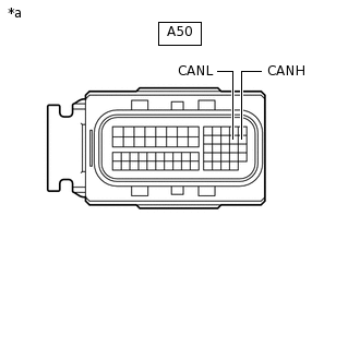
*a
Front view of wire harness connector
(to ECM)
Disconnect the A50 ECM connector.
Measure the resistance according to the value(s) in the table below.
Standard Resistance
Tester Connection
Condition
Specified Condition
A50-26 (CANH) - A50-25 (CANL)
Cable disconnected from negative (-) battery terminal
108 to 132 Ω
Result
Result
Result
OK
NG
NG REPAIR OR REPLACE CAN MAIN BUS LINE OR CONNECTOR (ECM MAIN LINE)
CHECK ECM POWER SOURCE CIRCUIT
Check the ECM power source circuit.
Result
Result
Result
OK
NG
NG REPAIR OR REPLACE HARNESS OR CONNECTOR (POWER SOURCE CIRCUIT)
CHECK FOR OPEN IN CAN BUS LINES (ECM MAIN LINE)
Disconnect the cable from the negative (-) battery terminal.
-
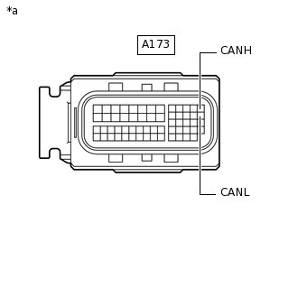
*a
Front view of wire harness connector
(to ECM)
Disconnect the A173 ECM connector.
Measure the resistance according to the value(s) in the table below.
Standard Resistance
Tester Connection
Condition
Specified Condition
A173-13 (CANH) - A173-26 (CANL)
Cable disconnected from negative (-) battery terminal
108 to 132 Ω
Result
Result
Result
OK
NG
NG REPAIR OR REPLACE CAN MAIN BUS LINE OR CONNECTOR (ECM MAIN LINE)
CHECK ECM POWER SOURCE CIRCUIT
Check the ECM power source circuit.
Result
Result
Result
OK
NG
NG REPAIR OR REPLACE HARNESS OR CONNECTOR (POWER SOURCE CIRCUIT)