AIRBAG SYSTEM SRS Warning Light Remains ON
DESCRIPTION
The SRS warning light is located on the combination meter.
When the SRS is normal, the SRS warning light comes on for approximately 6 seconds after the ignition switch is turned from LOCK to ON position, and then goes off automatically.
If there is a malfunction in the SRS, the SRS warning light comes on to inform the driver of a problem.
When terminals TC and CG of the DLC3 are connected, the DTC is displayed blinking the SRS warning light.
The SRS is equipped with a voltage-increase circuit (DC-DC converter) in the center airbag sensor assembly in case the source voltage drops.
When the battery voltage drops, the voltage-increase circuit (DC-DC converter) functions to increase the voltage of the SRS to normal voltage.
A malfunction in this circuit is not recorded in the center airbag sensor assembly. The SRS warning light automatically goes off when the source voltage returns to normal.
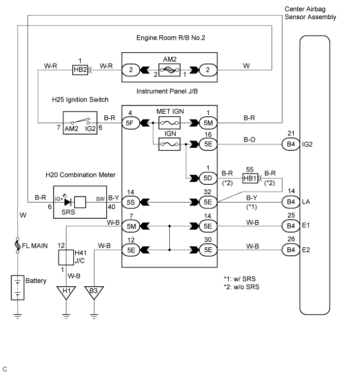
WIRING DIAGRAM
INSPECTION PROCEDURE
PROCEDURE
-
CHECK BATTERY
-
Measure the voltage of the battery.
Voltage 11 to 14 V
NG 
CHECK AND REPLACE BATTERY OR CHARGING SYSTEM
OK 
-
-
CHECK CONNECTORS
-
Turn the ignition switch to the LOCK position.
-
Disconnect the negative (-) terminal cable from the battery, and wait for at least 90 seconds.
-
Check that the connectors are properly connected to the center airbag sensor assembly and combination meter.
OK The connectors are connected.
NG
CONNECT CONNECTORS, THEN GO TO STEP 1
OK
-
-
CHECK WIRE HARNESS (SOURCE VOLTAGE OF CENTER AIRBAG SENSOR ASSEMBLY)
-
Disconnect the connectors from the center airbag sensor assembly.
-
Connect the negative (-) terminal cable to the battery, and wait for at least 2 seconds.
-
Turn the ignition switch to the ON position.
-
Operate all components of the electrical system (defogger, wipers, headlight, heater blower, etc.).
-
Measure the voltage according to the value(s) in the table below.
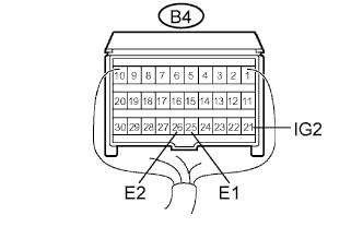
Voltage Tester connection Condition Specified condition B4-21 (IG2) -
Body ground
Ignition switch ON 10 to 14 V -
Turn the ignition switch to the LOCK position.
-
Measure the resistance according to the value(s) in the table below.
Resistance Tester connection Condition Specified condition B4-25 (E1) -
Body ground
Always Below 1 Ω B4-26 (E2) -
Body ground
Always Below 1 Ω
NG
REPAIR OR REPLACE WIRE HARNESS
OK
-
-
CHECK WIRE HARNESS (SOURCE VOLTAGE OF COMBINATION METER)
-
Disconnect the negative (-) terminal cable from the battery, and wait for at least 90 seconds.
-
Disconnect the connector from the combination meter.
-
Connect the negative (-) terminal cable to the battery, and wait for at least 2 seconds.
-
Turn the ignition switch to the ON position.
-
Measure the voltage according to the value(s) in the table below.
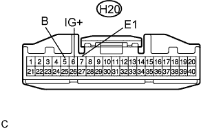
Voltage Tester connection Condition Specified condition H20-5 (B) -
Body ground
Ignition switch ON 10 to 14 V H20-6 (IG+) -
Body ground
Always 10 to 14 V -
Turn the ignition switch to the LOCK position.
-
Measure the resistance according to the value(s) in the table below.
Resistance Tester connection Condition Specified condition H20-7 (E1) -
Body ground
Always Below 1 Ω
NG
REPAIR OR REPLACE WIRE HARNESS
OK
-
-
CHECK SRS WARNING LIGHT
-
Turn the ignition switch to the LOCK position.
-
Disconnect the negative (-) terminal cable from the battery, and wait for at least 90 seconds.
-
Connect the connector to the combination meter.
-
Connect the negative (-) terminal cable to the battery, and wait for at least 2 seconds.
-
Turn the ignition switch to the ON position.
-
Check the SRS warning light condition.
OK After the primary check period, the SRS warning light goes off for approximately 10 seconds, and then comes on again. Tech Tips
The primary check period is for approximately 6 seconds after the ignition switch is turned to the ON position.
NG
GO TO COMBINATION METER SYSTEM
OK 
REPLACE CENTER AIRBAG SENSOR ASSEMBLY
-