SFI SYSTEM (w/ Dual VVT-i), Diagnostic DTC:P161A
| DTC Code | DTC Name |
|---|---|
| P161A | Lost Communication with Alternator |
DESCRIPTION
The ECM and generator assembly detect reception errors respectively.
| DTC No. | DTC Detection Condition | Trouble Area |
|---|---|---|
| P161A | A reception error in the ECM or generator assembly continues for approximately 5 seconds or more with the ignition switch ON. (1 trip detection logic) |
|
MONITOR DESCRIPTION
The generator assembly reception error detected by the generator assembly is sent to the ECM via LIN communication. If an error occurs in the ECM or generator assembly, the ECM determines there is a LIN communication error and stores this DTC.
MONITOR STRATEGY
| Frequency of Operation | Continuous |
CONFIRMATION DRIVING PATTERN
-
Connect the GTS to the DLC3.
-
Turn the ignition switch to ON and turn the GTS on.
-
Clear the DTCs (even if no DTCs are stored, perform the clear DTC procedure).
-
Turn the ignition switch off and wait for at least 30 seconds.
-
Turn the ignition switch to ON and turn the GTS on.
-
Wait 5 seconds or more.
-
Enter the following menus: Powertrain / Engine and ECT / Trouble Codes.
-
Read the pending DTCs.
Tech Tips
-
If a pending DTC is output, the system is malfunctioning.
-
If a pending DTC is not output, perform the following procedure.
-
-
Enter the following menus: Powertrain / Engine and ECT / Utility / All Readiness.
-
Input the DTC: P161A.
-
Check the DTC judgment result.
GTS Display Description NORMAL
-
DTC judgment completed
-
System normal
ABNORMAL
-
DTC judgment completed
-
System abnormal
INCOMPLETE
-
DTC judgment completed
-
Perform driving pattern after confirming DTC enabling conditions
N/A
-
Unable to perform DTC judgment
-
Number of DTCs which do not fulfill DTC preconditions has reached ECU memory limit
Tech Tips
-
If the judgment result shows NORMAL, the system is normal.
-
If the judgment result shows ABNORMAL, the system has a malfunction.
-
If the judgment result shows INCOMPLETE or N/A, perform the Confirmation Driving Pattern and check the DTC judgment result again.
-
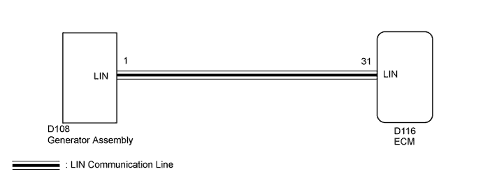
WIRING DIAGRAM
INSPECTION PROCEDURE
Tech Tips
Read freeze frame data using the GTS. Freeze frame data records engine conditions when a malfunction occurs. This information can be useful when troubleshooting.
PROCEDURE
-
CHECK CHARGING SYSTEM
-
Check the charging system Click here.
NG 
REPAIR OR REPLACE CHARGING SYSTEM
OK 
-
-
CHECK HARNESS AND CONNECTOR (GENERATOR - ECM)
-
Disconnect the generator connector.
-
Disconnect the ECM connector.
-
Measure the resistance according to the value(s) in the table below.
Standard Resistance Tester Connection Condition Specified Condition D108-1 (LIN) - D116-31 (LIN) Always Below 1 Ω D108-1 (LIN) or D116-31 (LIN) - Body ground Always 10 kΩ or higher
NG
REPAIR OR REPLACE HARNESS OR CONNECTOR
OK
-
-
INSPECT GENERATOR ASSEMBLY
-
Inspect the generator assembly Click here.
NG
REPLACE GENERATOR ASSEMBLY Click here
OK 
REPLACE ECM Click here
-