HYBRID CONTROL SYSTEM
-
SYSTEM CONTROL
-
Hybrid Vehicle Control
-
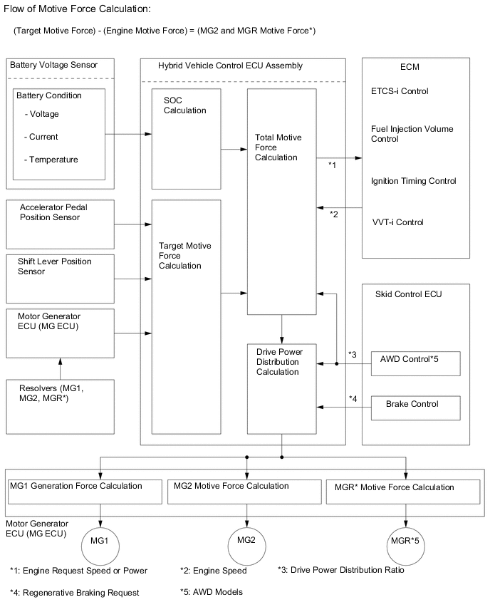
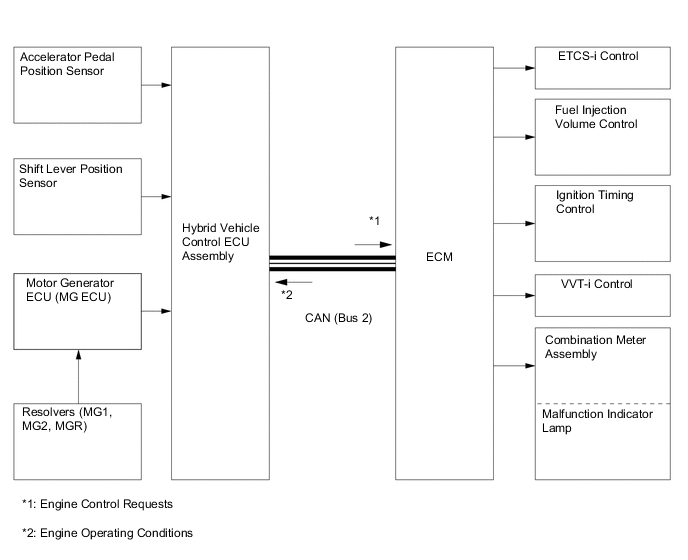
The hybrid vehicle control ECU assembly detects the degree to which the accelerator pedal is depressed using the signals from the accelerator pedal sensor assembly and detects the shift position signals from the shift lever position sensor. The hybrid vehicle control ECU assembly receives the speed signals from the generator (MG1) and motor (MG2) resolvers via the MG ECU. The hybrid vehicle control ECU assembly determines the driving conditions of the vehicle in accordance with this information, and optimally controls the motive forces of generator (MG1), motor (MG2) and the engine. Furthermore, the hybrid vehicle control ECU assembly optimally controls the output and torque of generator (MG1), motor (MG2) and the engine in order to deliver lower fuel consumption and cleaner exhaust emissions.
-
The hybrid vehicle control ECU assembly calculates the engine motive force based on the calculated target motive force, and by taking the State Of Charge (SOC) of the HV battery and the temperature of the HV battery into consideration. The value obtained by subtracting the engine motive force from the target motive force is the MG2 and MGR* motive force.
-
The ECM appropriately performs ETCS-i control, fuel injection volume control, ignition timing control and VVT-i system control based on signals sent by the hybrid vehicle control ECU assembly in order to achieve the required engine motive force. Furthermore, the hybrid vehicle control ECU assembly appropriately operates the MG1, MG2 and MGR* in order to achieve the required MG2 and MGR* motive force.
*: AWD models
-
-
System Monitoring Control
-
The hybrid vehicle control ECU assembly constantly monitors the State Of Charge (SOC) of the HV battery. When the SOC is below the lower level, the hybrid vehicle control ECU assembly increases the power output of the engine to operate MG1, which charges the HV battery. When the engine is stopped, MG1 operates to start the engine. Then, the engine operates MG1 to charge the HV battery.
-
If the SOC is low, or the temperature of the HV battery, MG1, MG2 or MGR* is higher than aspecified value, the hybrid vehicle control ECU assembly restricts the motive force applied to the drive wheels until the value of the abnormal item returns to normal.
*: AWD models
-
-
Shut Down Control
-
Generally, MG1 and MG2 are shut down when the shift lever is in N. In order to stop providing motive force, it is necessary to stop driving MG1 and MG2, because MG2 is mechanically joined to the front wheels. MGR will also be shut down at the same time.*
-
During driving, if the brake pedal is depressed and a wheel locks up, the ABS function isactivated. Afterwards, low torque is requested from MG2 or MGR* to provide supplemental power in order to restart the rotation of the wheel. Even if the shift lever is in N at this time, the shut down function is canceled to allow the wheel to rotate. After the wheel rotation has been restarted, the system resumes its shut down function.
-
When the vehicle is driven with the shift lever in D or S and the brake pedal is depressed, regenerative braking occurs. At this time, if the driver moves the shift lever to N, the brake hydraulic pressure increases while the request torque of the regenerative braking decreases gradually so as not to create a sluggish brake feel. The system then performs the shut down function.
-
When the speed of MG1, MG2 and MGR* is above a specified threshold, the shut down functionis canceled.
*: AWD models
-
-
System Main Relay Control
-
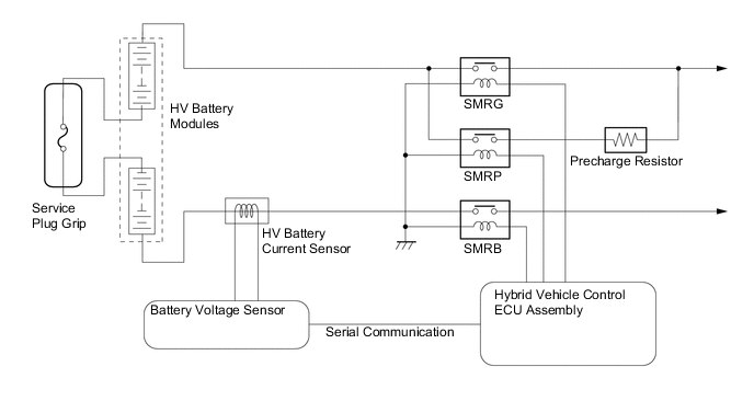
The System Main Relays (SMRs) are the relays that connect and disconnect the power source of the high-voltage circuit upon receiving a command from the hybrid vehicle control ECU Assembly.
-
A total of 3 relays, 1 for the positive side (SMRB), and 2 for the negative side (SMRP, SMRG), are provided to ensure proper operation.
-
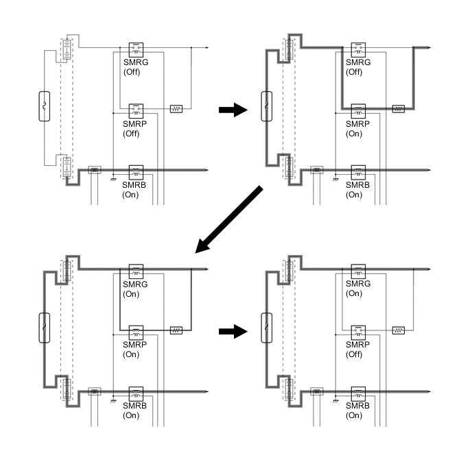
When the hybrid system changes to the READY-on state, the hybrid vehicle control ECU assembly turns on SMRB and SMRP in sequence, and applies the current through the precharge resistor. After that, it turns SMRG on, and applies the current by by passing the precharge resistor. Then it turns SMRP off. As the controlled current is initially allowed to pass through the precharge resistor in this manner, the contact point in the circuit is protected from damage that could be caused by an inrush current.
-
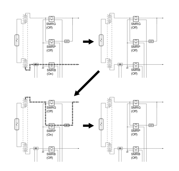
When the hybrid system changes to a state other than the READY-on state, the hybrid vehicle control ECU assembly turns SMRG off first. Next, it turns SMRB off after determining whether or not SMRG is operating properly. After that, it turns on SMRP and then off after determining whether or not SMRB is operating properly. As a result, the hybrid vehicle control ECU assembly verifies that the respective relays have been properly turned off.
-
-
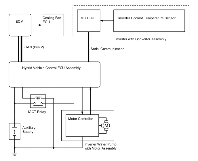
Inverter Coolant Cooling Control
-
The hybrid vehicle control ECU assembly receives the signal from the temperature sensor for the inverter coolant. Then, the hybrid vehicle control ECU assembly actuates the inverter water pump with motor assembly in 3 levels using duty cycle control, in order to cool the inverter coolant.
-
When the inverter coolant temperature rises above a certain level, the hybrid vehicle control ECU assembly transmits a radiator fan drive request signal to the cooling fan ECU via the ECM. Inresponse to the signal, the cooling fan ECU actuates the radiator fan to restrain the increases inthe inverter coolant temperature, ensuring the cooling of the inverter with converter assembly, MG1 and MG2.
-
The MG ECU converts the temperature sensor signal into a digital signal, and transmits the signal to the hybrid vehicle control ECU assembly via serial communication.
-
-
ECM Control
-
The ECM receives the target engine speed and required engine motive force which weresent from the hybrid vehicle control ECU assembly, and controls the ETCS-i system, fuel injection volume, ignition timing and VVT-i system.
-
The ECM transmits the operating condition of the engine to the hybrid vehicle control ECU assembly.
-
Upon receiving an engine stop signal from the hybrid vehicle control ECU assembly inaccordance with basic LEXUS Hybrid Drive control, the ECM will stop the engine.
-
When a malfunction occurs in the system, the ECM activates the Malfunction Indicator Lamp(MIL) via the directions from the hybrid vehicle control ECU assembly.
-
-