WORK NOTICES AND PRECAUTIONS PRECAUTIONS FOR REPAIRING ALUMINUM ALLOY PANELS
-
PORTIONS WHERE ALUMINUM ALLOY PANELS ARE USED
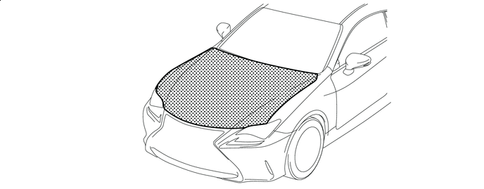

Al-Mg-Si Alloy (6000 series) - - -
WORK SAFETY
Although aluminum is a nontoxic material, it is very light in weight, which can easily cause metal particles to become airborne during sanding. It is important for technicians to protect their lungs and eyes from these particles.
It is the personal responsibility of the technicians to be aware of the dangers involved, and to protect themselves by using proper safety equipment. It is also necessary to provide adequate lighting and ventilating facilities in the workshop.
Please follow the recommended safety precautions below when repairing aluminum panels.
-
Always wear protective glasses, ear plugs, dust masks, and other protective equipment to protect your eyes, ears, and respiratory system.
-
Make sure to wear protective gloves when conducting heat repairs and when sanding or using organic solvents.
-
As safety equipment for an emergency, have fire extinguishers, first aid kits, and an eye wash area at the workplace.
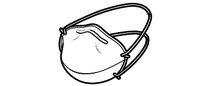
Dust mask (Disposable type) 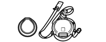
Dust mask (Exchange type) 
Face protector 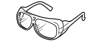
Safety glasses 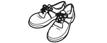
Safety shoes 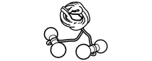
Ear plugs 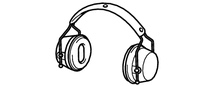
Ear protectors 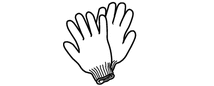
Cotton gloves 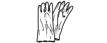
Solvent gloves - - -
-
DIFFERENCE BETWEEN 5000 SERIES AND 6000 SERIES ALUMINUM ALLOY PANELS
Type Heating Limit Temperature Proper Heating Temperature for Repairs AI-Mg Alloy (5000 series) 300°C (572°F) 250°C (482°F) AI-Mg-Si Alloy (6000 series) 250°C (482°F) 200°C (392°F) Note
There is a marked decrease in the panel strength if heated over the heating temperature limit.
-
CHARACTERISTICS OF ALUMINUM ALLOY
-
If the base metal of aluminum alloy is left untreated, it will naturally develop an oxide film that will protect against corrosion. As a result, an anti-rust agent does not need to be used even when aluminum alloy is exposed to heat during shrinking.
-
Aluminum alloy conducts heat very well so a wide area will become heated when heat is applied to one area.
- Aluminum Iron Heat Conductance 236 W/m*K 84 W/m*K -
Aluminum alloy does not become magnetized.
-
-
PRECAUTIONS WHEN CONDUCTING REPAIRS
-
If aluminum comes into contact with another type of metal (especially steel), galvanic corrosion will cause the base metal to corrode. If tools used to repair steel panels are not cleaned before they are used on aluminum alloy surfaces, the tools will leave behind steel particles and corrode the base metal.
Therefore make sure to completely clean off iron particles on the surface of tools if using them to repair steel parts before use, or prepare a separate set of tools (hammers, dollies, chisels, air sander, carbon electrode, etc.) for use on aluminum alloys only.
Tech Tips
Galvanic corrosion is rusting that is created by a potential difference between two metals that is produced when they come in to contact together. This phenomenon occurs with any type of metal, and the aluminum causes the corrosion when the base metal surfaces of aluminum and steel are put together.
-
An oxide film forms on an aluminum alloy within a matter of minutes when the base metal is exposed to the air.
This oxide film has a negative effect on putty and paint adhesion, so it is important to immediately treat the base metal after sanding and degreasing.
-
Aluminum is brittle and easily develops work hardening and cracks. Heating aluminum when restoring a deformed portion improves workability and prevents work hardening and cracking so it is an effective method when repairing.
However, heating at the optimal heating temperature provides the very best results and any increase in temperature above this will result in a corresponding decrease in strength. (There is a marked decrease in strength if the optimal heating temperature is exceeded.)
-
-
CHOOSING THE REPAIR METHOD
- Damaged Condition Judgment Criteria Repair method Repairable*1 A dent on the flat outer panel surface
-
There is no plastic deformation to the outer panel.
-
There is no deformation to the ends of the outer panel.
-
No deformation to the inner panel.
-
No separation between outer and inner panel.
Repair by pulling. Deformation to the outer or inner panels.
-
Slight plastic deformation to the outer and inner panels. (Deformation that does not crack while repairing.)
-
No separation between outer and inner panel.
Repair with a hammer and dolly by heating. Not Repairable Tears and hole openings - Replacement of the assembly. Damage with severe plastic deformation*2 *1: The repairable size of the damage is judged by the same standard as for steel panels.
*2: Not repairable because cracking will occur while repairing.
-
-
THE WORK PROCEDURE OF EACH REPAIR METHOD (Repair by Pulling)
Recommended tools 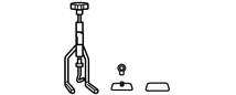
Puller 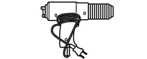
Industrial heater gun 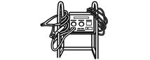
Washer welder (For use on standard steel panels) 
Carbon electrode 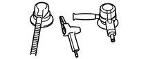
Air tools 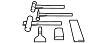
-
Plastic-faced hammer
-
Fine smoothening hammer
-
Wooden hammer
-
Dolly
-
Body line chisel and wood piece
Note
Make sure to completely clean off iron particles on the surface of the tools above if using them to repair steel parts before use, or prepare a separate set of tools for use on aluminum alloys only (to prevent galvanic corrosion of the aluminum).
-
CHECK OF THE DAMAGE
-
Inspect visually and brush your hand across the damaged surface to determine the condition of the damaged area and whether there is any stretching. Also, check for any cracking and paint peeling. In cases where no paint defects are found, conduct the work starting from (c).
-
-
PAINT REMOVAL (NOT NECESSARY IN CASES WHERE THERE ARE NO PAINT DEFECTS)
-
Completely remove the paint at the points where bonding chips will be attached.
-
-
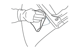
DEGREASING WHERE THE BONDING CHIP WILL BE ATTACHED
-
After air blowing the surface, apply the degreaser cleaning solution that comes with the puller set to a cloth and degrease the area to be repaired.
Tech Tips
If there are no paint defects present, scuff with the extra fine compound and then degrease.
-
-
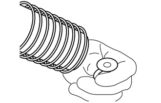
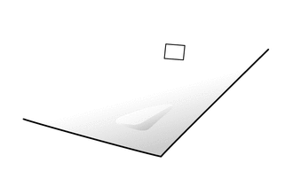
PREPARING THE PLATE HOOK
-
Heat the plate hook with an industrial heater gun and attach the bonding chip before it cools off.
-
-
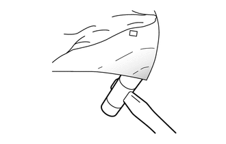
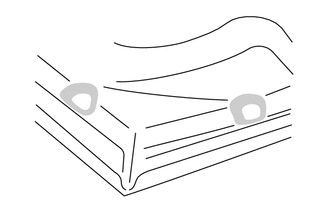
SETTING THE PLATE HOOK
-
Attach two-sided tape (or masking tape folded over on itself) on the back of the magnet for positioning and set the plate hook on the panel surface to secure it in place.
Tech Tips
The magnet must be attached with tape because aluminum does not magnetize.
-
-
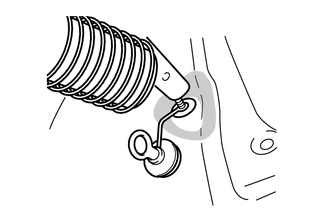
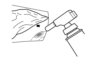
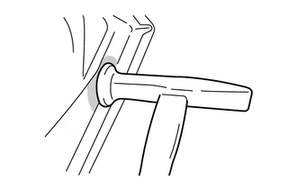
ATTACHING THE PLATE HOOK
-
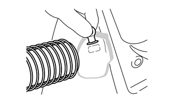
Heat the bonding chip with an industrial heater gun. Then use a handle of a hammer or the like to apply pressure on the plate hook and adhere it to the surface.
-
Next, air blow to cool down the panel surface and plate hook.
-
-
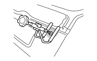
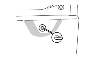
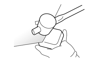
SETTING THE PULLER
-
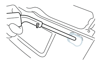
Fasten the magnet rubber plate attachment under the arm of the puller (with tape or the like) to prevent secondary damage.
-
Attach the eye nut to the plate hook and then attach the puller hook to the eye nut. Pull outward to about 1 to 2 mm (0.04 to 0.08 in.) past the height of the undamaged surface.
-
-
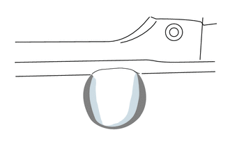
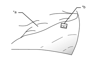
PULLING
-
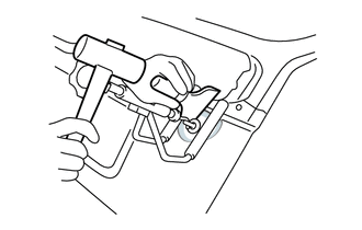
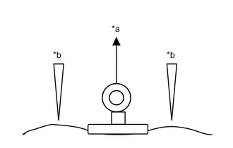
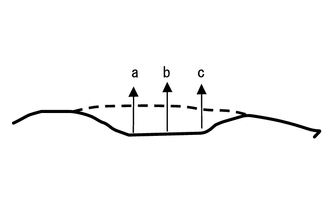
*a Pull *b Strike While keeping the puller pulled outward, lightly strike the convex surrounding area with a body line chisel or wood piece.
Tech Tips
Perform procedures (d) to (i) for areas a, b and c in alphabetical order. Pull so that each area is -1 to -2 mm (-0.04 to -0.08 in.) in relation to the undamaged surface.
-
-
REMOVING THE PLATE HOOK
-
After pulling, use an industrial heater gun to heat the bonding chip until it melts and then remove the plate hook.
-
Heat the leftover bonding chip and use a spatula to quickly remove it from the panel. Then apply the degreaser cleaning solution to degrease the panel surface.
Note
After the above work has been completed, conduct the following shrinking work if the tension of the repaired panel surface is inadequate.
-
-
SHRINKING
-
Shrink areas that are elevated due to stretching with a carbon electrode to ensure tension.
-
After shrinking, remove the burn mark in the same way as when repairing regular steel panels.
Note
-
There is a negative effect on putty adhesion of the exposed panel portions due to oxidization.
-
Create a featheredge on the previous coat, and apply primer and putty immediately after the shrinking work.
-
-
-
-
THE WORK PROCEDURE OF EACH REPAIR METHOD (Repairing with a Hammer and Dolly by Heating)
Recommended tools 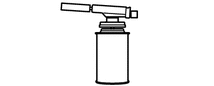
Gas burner Industrial heater gun 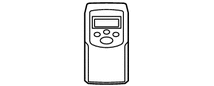
Noncontact thermometer 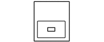
Temperature indication label
-
Plastic-faced hammer
-
Fine smoothening hammer
-
Wooden hammer
-
Dolly
-
Body line chisel and wood piece
- - Note
Make sure to completely clean off iron particles on the surface of the tools above if using them to repair steel parts before use, or prepare a separate set of tools for use on aluminum alloys only (to prevent galvanic corrosion of the aluminum).
-
CHECK OF THE DAMAGE
-
Inspect visually and brush your hand across the damaged surface to determine the condition of the damaged area and whether there is any stretching.
-
-
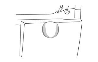
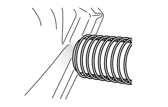
*a Wet cloth *b Temperature indication label PREPARATION FOR HEAT REPAIRS
-
Cover the undamaged paint coating with a wet cloth so that it will not be burned by the flame of the burner while heating.
-
Put the temperature indication label at a position approximately 50 mm (1.97 in.) away from the heated area.
Tech Tips
Position the temperature indication label so that it is not directly exposed to the burner flame.
-
-
HEAT REPAIRING
-
Evenly heat the bent portion.
Note
-
Do not directly expose the temperature indication label to the flame.
-
Stop heating before the temperature indication label color changes.
-
Measure the painted surface when using a noncontact thermometer. (The aluminum base metal surface cannot be precisely measured.)
-
Apply a guide coat or a lacquer coat (white or black) on the base metal surface and then measure the surface to be painted when measuring the aluminum base metal surface.
-
The temperature will rise immediately after heating so make sure to frequently measure the temperature. (There is a large marked decrease in strength if the heating limit temperature is exceeded.)
- Temperature Gas torch flame 1300°C (2372°F) Maximum Aluminum alloy panel heating limit temperature 300°C (572°F) Al-Mg Alloy (5000 series) 250°C (482°F) Al-Mg-Si Alloy (6000 series) Aluminum alloy panel optimal heating temperature 250°C (482°F) Al-Mg Alloy (5000 series) 200°C (392°F) Al-Mg-Si Alloy (6000 series) Aluminum melting point About 650°C (1202°F) -
-
-
REPAIRING BY HAMMERING
-
Rough Repairing
Aluminum quickly cools down after being heating so hammer the backside of panel with a plasticfaced or wooden hammer immediately after heating.
-
Guidelines for Finishing Rough Repair
Even if there is unevenness in the surface, the repair is complete if the edge lines are restored.
-
Repair with a Hammer and Dolly
-
Smooth the surface repeatedly using an on-dolly and an off-dolly on the surface.
-
Restore the panel edge line with an on-dolly.
-
-
-
CHECK OF THE REPAIRED SURFACE
-
Check the following two conditions and repair by shrinking using a carbon electrode if either applies.
-
There is an area that is higher than normal.
-
There is inadequate tension.
-
-
-
REPAIRING DENTS ON THE INNER PANEL PORTION
-
If there are no high points, repair by putty shaping.
-
If there are high points, place the nozzle of an industrial heater gun close to the high point, and heat it for 30 seconds.
-
Repair the shape of the surface with a fine smoothening hammer before the heated portion cools off.
Tech Tips
Alternate between heating and hammering.
-
-
PROCEDURE AFTER PANEL REPAIR (PUTTY SHAPING, PAINTING, ETC.)
-
Conduct the procedure based on the work process below. (The basic work process is the same as for repairs on steel panels.)
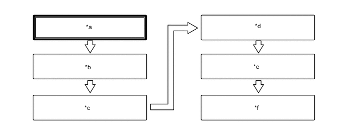
*a Panel repairs *b Featheredging, Scuffing *c Primer application *d Putty shaping *e Primer surfacer application *f Top coating Tech Tips
Perform the procedure with the paint manufacture specified primer and putty. Also, when using the primer and putty, make sure to follow the paint manufacturer's instructions.
-
-