CYLINDER BLOCK DISASSEMBLY
PROCEDURE
REMOVE NO.1 BALANCESHAFT
-
*1
Cap
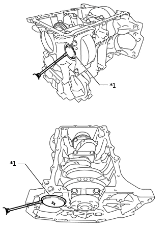
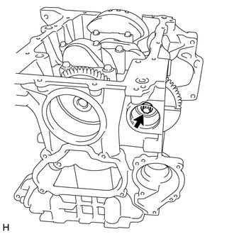
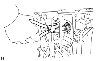
Using a screwdriver with its tip wrapped with protective tape, remove the cylinder block tight plugs.
-
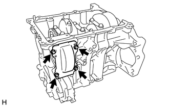
Remove the 4 bolts and cylinder block side cover from the cylinder block sub-assembly.
-
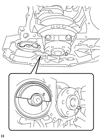
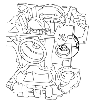
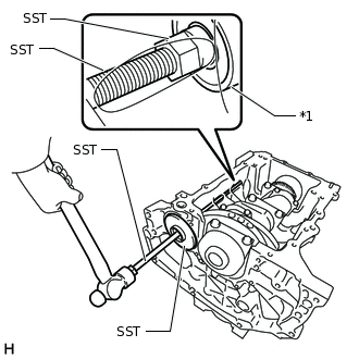
Turn the crankshaft and No. 1 balanceshaft so that they are positioned as shown in the illustration.
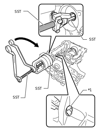
Using SST, secure the crankshaft and No. 1 balanceshaft.
0109-4
0109-4B
Note:Check that SST is correctly positioned on the No. 1 balanceshaft as shown in the illustration.
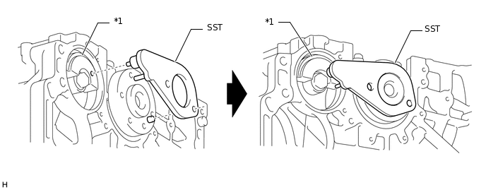
*1
No. 1 Balanceshaft
-
-
-
Using an E12 "TORX" socket wrench, remove the bolt.
-
Remove the balance weight and No. 1 balanceshaft driven gear.
-
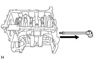
Remove the No. 1 balanceshaft as shown in the illustration.
-
REMOVE NO. 1 AND NO. 2 BALANCESHAFT BEARING
-
*1
No. 1 Balanceshaft Bearing
Using SST, remove the No. 2 balanceshaft bearing.
09612-65014
09387-01021
09527-17011
-
Remove the stop-ring.
-
*1
No. 2 Balanceshaft Bearing
Using SST, remove the No. 1 balanceshaft bearing.
0109-4
0109-4F
-
REMOVE PISTON WITH CONNECTING ROD
-
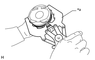
*a
Ridge Reamer
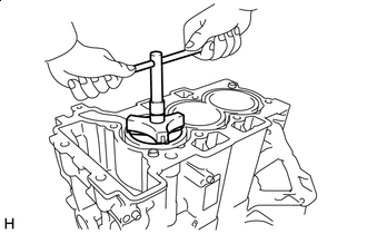
Using a ridge reamer, remove all the carbon from the top of the cylinder.
Remove the 6 connecting rod bolts, 3 connecting rod caps and 3 connecting rod bearings.
Push the piston, connecting rod and connecting rod bearing through the top of the cylinder block sub-assembly.
Tip:Keep the connecting rod bearings, connecting rod and connecting rod cap together.
Be sure to arrange the removed piston and connecting rod in such a way that they can be reinstalled exactly as before.
-
REMOVE CONNECTING ROD BEARING
Remove the connecting rod bearings from the connecting rod sub-assemblies and connecting rod caps.
Tip:Arrange the removed parts in the correct order.
INSPECT CRANKSHAFT THRUST CLEARANCE
-
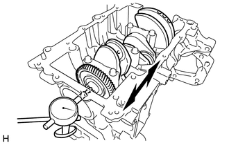
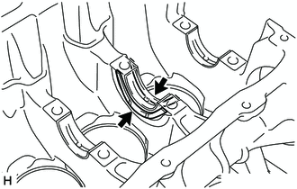
Using a dial indicator, measure the thrust clearance while prying the crankshaft back and forth with a screwdriver.
Standard Thrust Clearance
0.07 to 0.42 mm (0.00276 to 0.0165 in.)
If the thrust clearance is more than the maximum, replace the crankshaft thrust washers as a set. If necessary, replace the crankshaft.
Standard Thrust Washer Thickness
2.35 mm (0.0925 in.)
-
REMOVE CRANKSHAFT
-
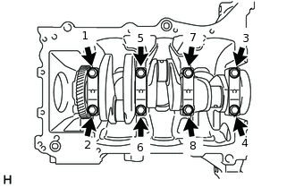
Uniformly loosen and remove the 8 crankshaft bearing cap bolts in several steps in the order shown in the illustration.
Remove the 4 crankshaft bearing caps from the cylinder block sub-assembly.
Tip:Keep the No. 2 crankshaft bearings and crankshaft bearing caps together.
Arrange the removed parts in the correct order.
Remove the crankshaft from the cylinder block sub-assembly.
Tip:Keep the crankshaft bearings and crankshaft thrust washers together with the cylinder block sub-assembly.
Check each crankshaft journal and crankshaft bearing for pitting and scratches.
If the journal or crankshaft bearing is damaged, replace the crankshaft bearings. If necessary, replace the crankshaft.
-
REMOVE CRANKSHAFT THRUST WASHER
-
Remove the 2 crankshaft thrust washers from the cylinder block sub-assembly.
-
REMOVE CRANKSHAFT BEARING
Remove the 4 crankshaft bearings and 4 No. 2crankshaft bearings from the cylinder block sub-assembly and crankshaft bearing caps.
Tip:Arrange the removed parts in the correct order.
REMOVE PISTON RING SET
-
*a
Piston Ring Expander
Using a piston ring expander, remove the No. 1 compression ring and No. 2 compression ring.
Remove the oil ring and oil ring expander by hand.
Tip:Arrange the removed parts in the correct order.
-
REMOVE PISTON
Gradually heat each piston to approximately 100 °C (212 °F).
-
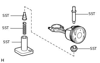
Using SST, press out the piston pin from thepiston. Remove the piston.
09221-25026
09221-00021
09221-00030
09221-21010
09221-02100
09221-02200
09221-02300
Tip:The piston and piston pin are amatched set.
Be sure to arrange the removed pistons, piston pins, piston rings, connecting rod sub-assemblies and connecting rod bearings in such a way that they can be reinstalled exactly as before.